Aerial oil receiving guide control method based on machine vision

A guidance control and machine vision technology, applied in the field of aviation flight control, can solve the problems of not meeting the accuracy requirements of automatic aerial refueling, increasing the pilot's manipulation burden, and low success rate

Active Publication Date: 2014-11-05
SHENYANG AIRCRAFT DESIGN INST AVIATION IND CORP OF CHINA
View PDF1 Cites 15 Cited by
  • Summary
  • Abstract
  • Description
  • Claims
  • Application Information

AI Technical Summary

Problems solved by technology

[0004] In this process, in the selection of navigation methods, when the distance between the refueling and refueling machines is relatively long (about 3.2km), traditional inertial navigation and GPS navigation are often used to guide the refueling machine to approach the refueling machine. Accurate refueling formation; when the distance between the two aircraft is relatively close (generally within 100m)

Method used


Image

  • Aerial oil receiving guide control method based on machine vision
  • Aerial oil receiving guide control method based on machine vision
  • Aerial oil receiving guide control method based on machine vision

Examples


Embodiment Construction

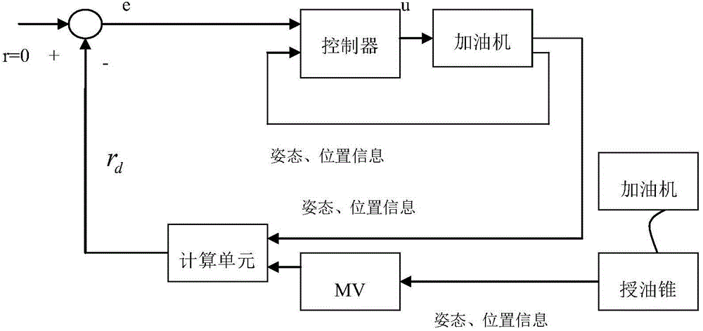
[0036] The present invention will be further described in detail below through specific control strategies in conjunction with the accompanying drawings.

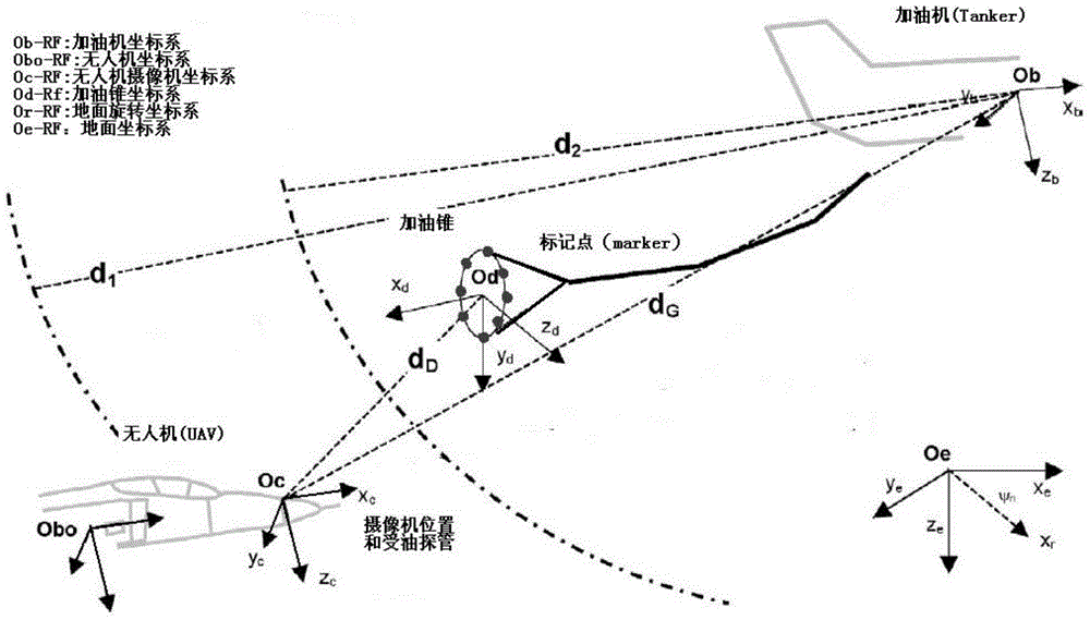
[0037] Assuming that the fuel dispenser is flying straight and level at a constant height and constant speed, an auxiliary optical mark is installed on the fueling cone of the fuel dispenser, and a camera is installed on the fuel receiver.

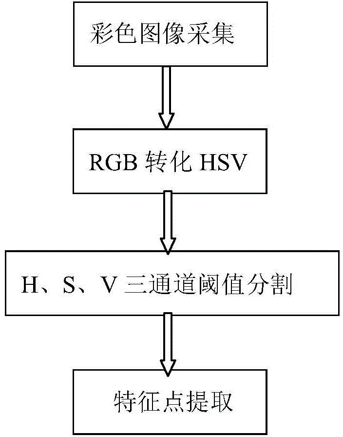
[0038] The first is to define the coordinate system where the fuel dispenser, receiver, fuel cone, and camera are located, and describe the geometric pose relationship through the transformation between each coordinate system. Set the relative distance of the visual fuel cone as: X=-1.4m, Y=0.5m, Z=5.6m, such as figure 1 Shown. Through the color space (RGB) to hue, saturation, and lightness (HSV) processing of the image collected by the camera, the images of the three channels of H, S, and V, and the H and S channel images are selected for the given threshold segmentation. The target point...


PUM


Abstract

The invention belongs to the technical field of flying control, and particularly relates to an aerial oil receiving guide control method based on machine vision. The method aims at an airplane with oil adding and oil receiving functions so as to broaden the range of fighting and improve the possibility of successful recovery. The method is characterized in that the key point for realizing aerial oil adding is that the relative position between an oil adding cone tube and an oil receiving plane is accurately measured and effective guide and control are carried out on the oil receiving plane. As for a vision guide system, two main components of vision navigation and guide control can be divided. Supposed the oil adding plane flies at the set height at a constant speed and in a straight line, an auxiliary optical marker is arranged on the oil adding cone tube of the oil adding plane, a camera is arranged on the oil receiving plane, the position and the gesture of the oil adding cone tube can be measured in real time by adopting the vision measurement technology, a proper flight control rate is designed to guide the oil receiving plane, and oil adding and docking can be finished. According to the aerial refueling guide control method based on machine vision, the method is suitable for features of the oil receiving task, the operation burdens of a pilot during the oil receiving task process are reduced, and the success rate of the oil receiving task can be greatly improved.

Description

Technical field [0001] The invention belongs to the technical field of aviation flight control, and in particular relates to an airborne fuel guidance control method based on machine vision guidance. Background technique [0002] To put it simply, aerial refueling technology is a technology that refuels another or several aircraft (or helicopters) in the air to increase its range and endurance. [0003] Traditional refueling methods include hose-floating anchor refueling method, flying spar (hard tube) refueling method, and a hybrid method that combines the above two methods. Regardless of whether the aerial refueling machine adopts any of the above aerial refueling equipment or operating methods, the process is roughly as follows: First, the refueling machine and the receiving machine must meet at a predetermined place at a predetermined time before the aerial refueling operation can be carried out. Then the oil receiver and the fuel dispenser are connected. After the connection ...

Claims


Application Information

Patent Timeline
IPC IPC(8): G05D1/10
Inventor 范彦铭张杨杨宁邵铮
Owner SHENYANG AIRCRAFT DESIGN INST AVIATION IND CORP OF CHINA
Why Eureka
Try Eureka