An operating device for a multi-pole miniature circuit breaker

A technology for small circuit breakers and operating devices, which is applied in emergency protection devices, protective switch operation/release mechanisms, circuits, etc. The effect of reducing the breaking force, reducing the volume, and reducing the width dimension

Active Publication Date: 2016-03-02
CHINT GROUP CORPORATION +1
View PDF11 Cites 0 Cited by
  • Summary
  • Abstract
  • Description
  • Claims
  • Application Information

AI Technical Summary

Problems solved by technology

If the above-mentioned operating mechanism technology is used, two operating mechanisms need to be arranged in parallel for a two-pole circuit breaker, and multiple operating mechanisms should be arranged in parallel for a multi-pole circuit breaker. Obviously, the increasingly urgent requirements for miniaturization and high breaking capacity of circuit breakers cannot be realized.
However, if two poles share one operating device, that is, one operating device controls the closing / breaking of the moving contacts and static contacts of the two poles, it can obviously reduce the size of the circuit breaker product, but the existing multi-pole or single-pole small Under the constraints of modularization standards, the circuit breaker has a very compact structure, and the following technical problems need to be solved in the already crowded internal space: First, the operating device must synchronously control the two moving contacts and the two static contacts respectively. Closing / breaking, and the contact pressure between the two moving contacts and the two static contacts is equal; the second is that the operating device must be mechanically coupled with the two electromagnetic tripping devices, and the tripping of any one of the electromagnetic tripping devices The action can reliably cause the operating device to trip and trip; the third is that the operating device must be mechanically coupled with the two thermal trip devices, and the tripping action of any one of the thermal trip devices can reliably cause the operating device to trip and trip

Method used


Image

  • An operating device for a multi-pole miniature circuit breaker
  • An operating device for a multi-pole miniature circuit breaker
  • An operating device for a multi-pole miniature circuit breaker

Examples


Embodiment Construction

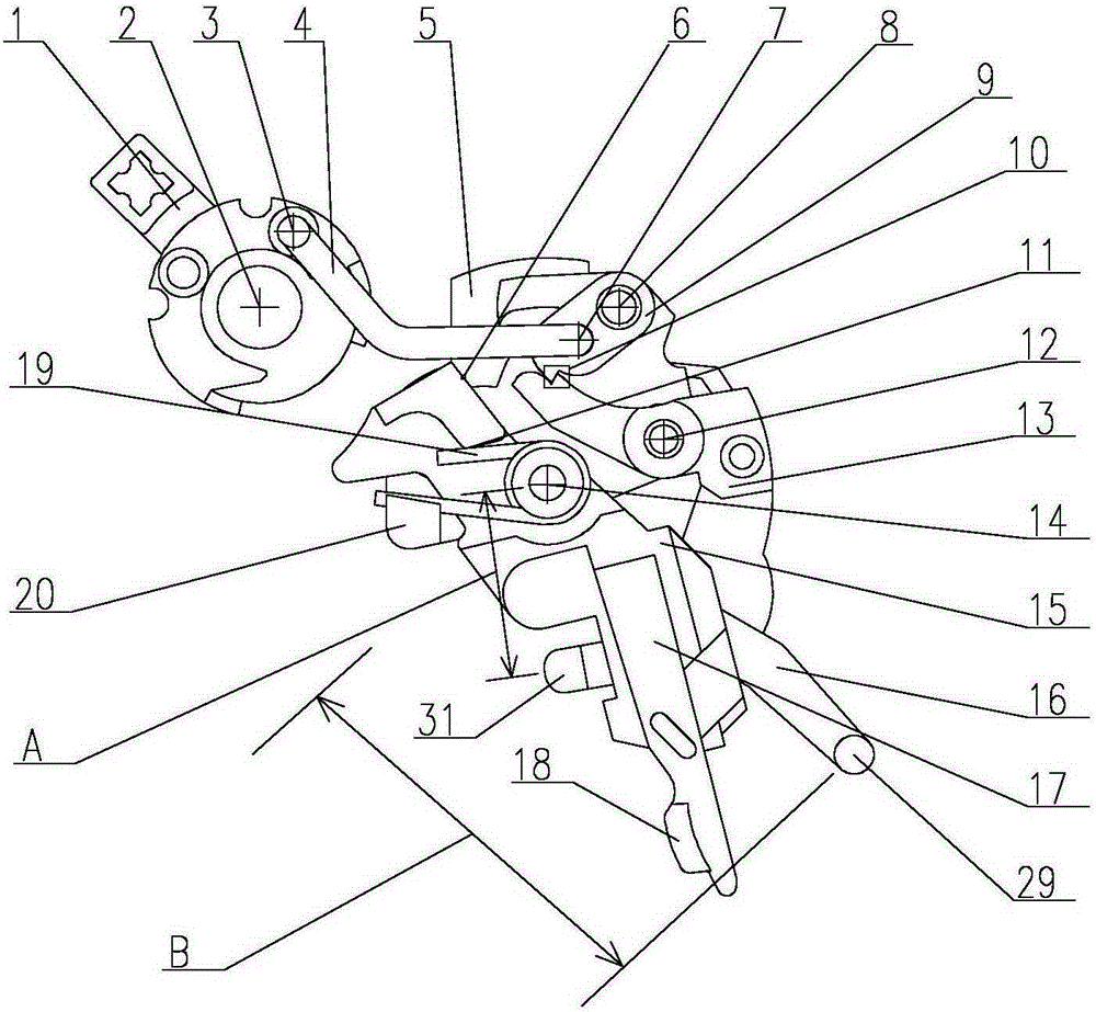
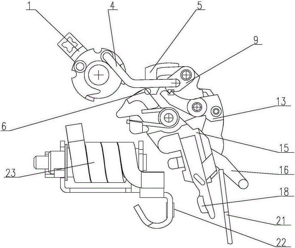
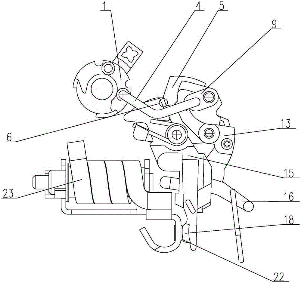
[0025] Combine below Figure 1 to Figure 6The given examples further illustrate the specific implementation of the operating device for the multi-pole miniature circuit breaker of the present invention. The operating device of the multi-pole miniature circuit breaker of the present invention is not limited to the description of the following embodiments.

[0026] Such as figure 1 As shown in the structural schematic diagram of the multi-pole miniature circuit breaker of the present invention, the operating device of the multi-pole miniature circuit breaker of the present invention is installed in the insulating housing (not shown in the figure) of the circuit breaker, and mainly includes a handle 1, which is connected to the rotating shaft 2 on the housing. A U-shaped bar 4, a rotating plate 5 and a mechanical interlock 10 formed a four-bar linkage mechanism, the handle 1 is pivotally mounted on the insulating case of the circuit breaker through the rotating shaft 2, and the ...


PUM


Abstract

The operating device of the multi -pole small circuit breaker, including the handle, the rotor board that is passed on the shell through the stomat axis, two pairs of closed / dubbing contacts, and two electromagnetic deduction devices and thermal deduction device set by side parallel settingsEssenceThe lock -locking connecting rod is on the rotating board through the first twisted pivot; the brake rod on the rotor board through the second twisted pivot is provided with tooth locks, which can be electromagnetic with adjacent two poles, respectively.The control element cooperated with the deduction device and the bi -metal sheet that can be combined with the thermal device of the adjacent bipolar breaker, respectively.The short -circuit and short columns set on the side of the manipulation component are touched with two electromagnetic deduction devices.The film touches the cooperation.The cards can be controlled by two adjacent groups of independent off -device, with small size, compact structure and more reliable movements.

Description

technical field [0001] The present invention relates to a low-voltage miniature circuit breaker, in particular to an operating device for a miniature circuit breaker, in particular to an operating device for a multi-pole miniature circuit breaker. A two-pole circuit breaker consisting of a tripping device and an openable contact group associated with an operating device may also be a multi-pole circuit breaker that is coordinated by two or more operating devices. Background technique [0002] General low-voltage circuit breakers, especially the operating mechanism of terminal miniature circuit breakers, have modular standard requirements for their dimensions, and also require short-circuit protection and overload protection functions. In addition, there are often requirements for residual current action protection. For this reason , most of the existing multi-pole miniature circuit breakers adopt an assembled structure, and a plurality of single-pole miniature circuit breake...

Claims


Application Information

Patent Timeline
Patent Type & Authority Patents(China)
IPC IPC(8): H01H71/10
CPCH01H71/10H01H71/002H01H71/526H01H71/123
Inventor 周长青夏晓敏于利英
Owner CHINT GROUP CORPORATION
Why Eureka
Try Eureka