
CT machine part connecting system based on back board

A connection system and board-to-board connector technology, applied to electrical components, X-ray equipment, etc., to achieve simple and fast cable connection, improve reliability, improve signal interference and shielding problems

Inactive Publication Date: 2014-11-05
JIANGSU SINOGRAM MEDICAL TECH
View PDF0 Cites 1 Cited by
  • Summary
  • Abstract
  • Description
  • Claims
  • Application Information

AI Technical Summary

Problems solved by technology

[0004] In order to solve the above existing technical problems, the present invention proposes a backplane-based CT machine component connection structure, which can effectively solve various problems caused by traditional connection designs

Method used


Image

  • CT machine part connecting system based on back board
  • CT machine part connecting system based on back board

Examples


Embodiment Construction

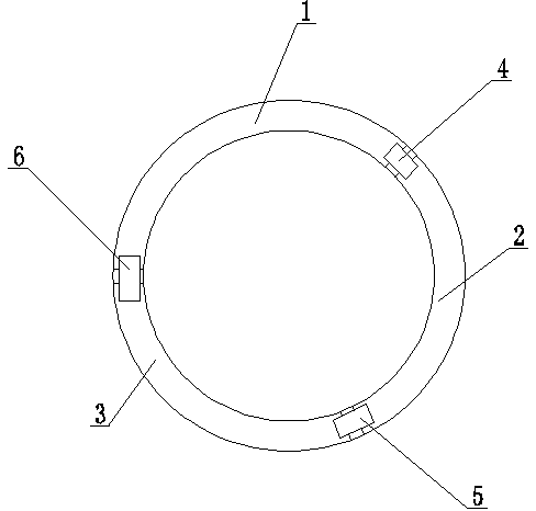
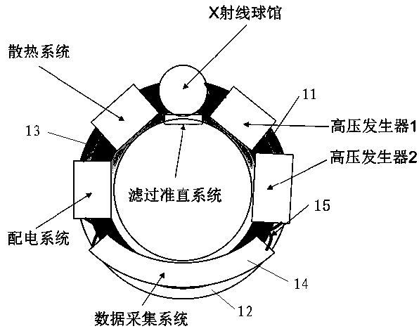
[0013] Such as figure 1 As shown, the annular circuit backplane 11 of the present invention is composed of three arc-shaped backplanes 1, 2, 3 printed with circuits and three inter-board connectors 4, 5, 6 provided with circuits.

[0014] The three sections of arc-shaped backplanes 1, 2, and 3 are arranged circularly in turn to form a circular ring, and the inter-board connector 4 is arranged between adjacent arc-shaped backplanes 1 and 2, and the two ends of the inter-board connector 4 They are respectively connected to two arc-shaped backplanes 1 and 2, and the inter-board connector 5 is arranged between the adjacent arc-shaped backplanes 3 and 3, and the two ends of the inter-board connector 5 are connected to the two arc-shaped backplanes respectively. 2 and 3 are connected, the inter-board connector 6 is arranged between the adjacent arc-shaped backplanes 1 and 3, and the two ends of the inter-board connector 6 are respectively connected to two arc-shaped backplanes 1 and...


PUM


Abstract

The invention provides a CT machine part connecting system based on a back board, and relates to the technical field of computed tomography system (CT instrument) production, in particular to the structure technique of a scanning rack of a computed tomography system. The ring circuit back board is arranged on one side of the rack. The CT machine part connecting system is characterized in that the ring circuit back board is composed of at least two sections of arc-shaped back board bodies on which circuits are printed; every two adjacent arc-shaped back board bodies are connected through an inter-board connector with a circuit, and then an annulus is defined by all the arc-shaped back board bodies; each arc-shaped back board body is provided with a part port.

Description

technical field [0001] The invention relates to the technical field of production of a computerized tomography system (CT instrument), in particular to the structural technology of its scanning frame. Background technique [0002] The computed tomography system is mainly composed of a scanning frame, a bed and a console. The scanning frame consists of a rotating part and a fixed support part, and the main image-related components are installed on the rotating part. These include X-ray tubes, high-voltage generators, temperature control systems, ray collimators, X-ray detectors, data acquisition systems and rotary master control units. There are data and power connections between the components and the main control unit and between the components. The current general practice is to use independent cables to connect each device body one by one. [0003] The above connection method brings several problems during use: 1. Since all the components are distributed on the ring me...

Claims


Application Information

Patent Timeline
IPC IPC(8): H05G1/02
Inventor 周宇任敬轶付诗农居小平王涛高飞郜文兵冯海友
Owner JIANGSU SINOGRAM MEDICAL TECH
Learn More