Charging electronic cigarette

A technology of electronic cigarettes and recharging, which is applied in the direction of tobacco, smoker supplies, inhalers, etc., can solve unrealistic problems

Inactive Publication Date: 2014-11-05
SIS RESOURCES LTD
View PDF7 Cites 26 Cited by
  • Summary
  • Abstract
  • Description
  • Claims
  • Application Information

AI Technical Summary

Problems solved by technology

It is unrealistic to use e-cigarettes to smoke while simultaneously charging the device without having to actually change the batteries

Method used


Image

  • Charging electronic cigarette
  • Charging electronic cigarette
  • Charging electronic cigarette

Examples


Embodiment 1

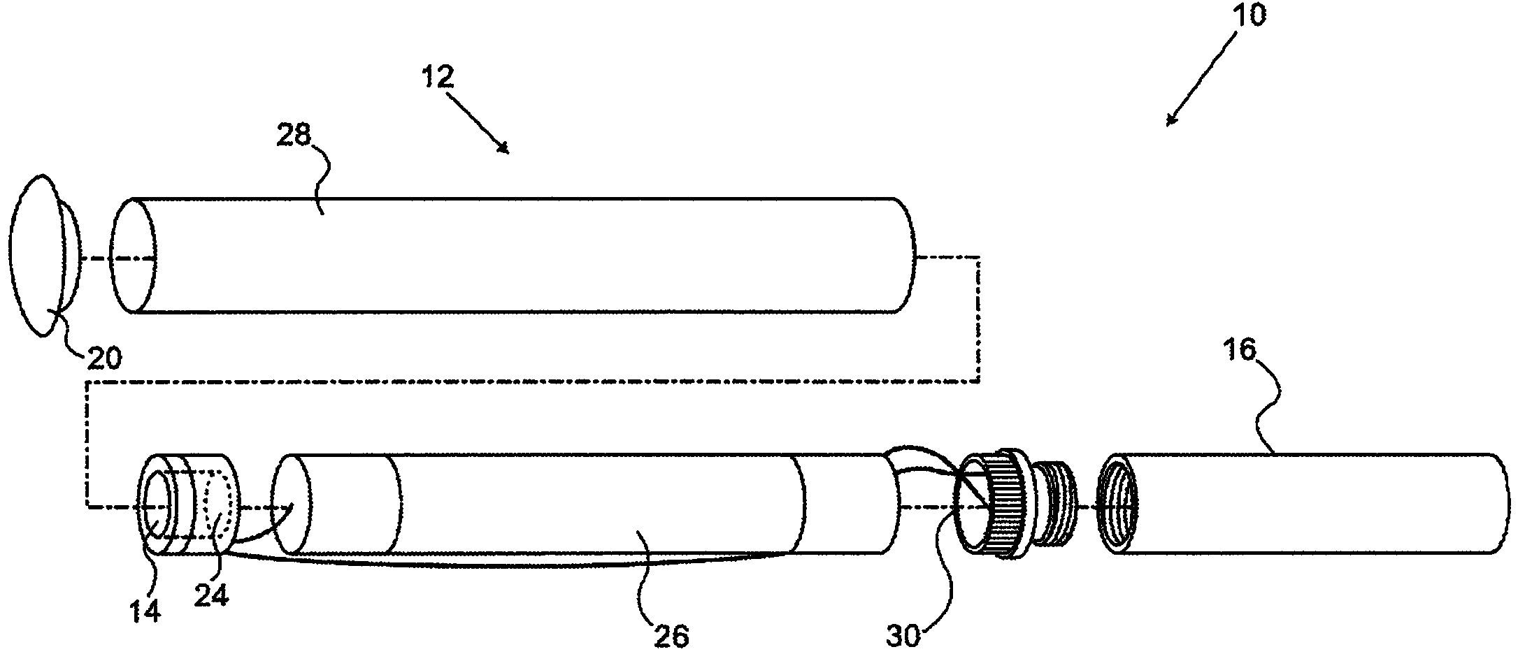
[0061] Now looking at the attached drawings, first refer to figure 1 , figure 1 is a semi-schematic exploded view of a smoking device 10 according to an embodiment of the invention. The device 10 has a cartridge that includes a battery portion 12 . The battery section 12 may include a power control circuit 14 that is typically packaged as a unit with a vacuum sensor 24 and may be enclosed in a plastic holder. Suitable power control circuits are disclosed in co-owned US Provisional Application No. 61 / 441,133, which is incorporated herein by reference. The device 10 includes a sleeve portion 16 having a nebulizer with a high resistance wire that heats the liquid or gel when the nebulizer is energized. The liquid is usually a mixture of nicotine, propylene glycol, vegetable glycerin, and flavoring. The components of the sleeve portion 16 are unitary as taught in co-owned US Provisional Application No. 61 / 474,569, which is incorporated herein by reference. In this case part...

Embodiment 2

[0084] now refer to Figure 14 , Figure 14 is a schematic diagram of an electrical circuit in an electronic cigarette 130 adapted to a battery charger according to another embodiment of the present invention. Through this embodiment, it is possible to connect an external charger while powering the atomizer. The battery charger assembly 96 is now connected to the side port 128 of the electronic cigarette 130 having the external contacts 132, 134 connected within the internal battery compartment 105 to the internal battery compartment 105 comprising the diode 108 and the battery 104 positive terminal 110 on the circuit. When sensor chip assembly 114 is activated as the user takes a puff, a switch (representatively shown as relay 136 ) is activated, thereby opening the charging circuit so that the charger is no longer operational. Of course, the relay 136 could be replaced by other types of switches such as transistors or field effect transistors. The sensor chip assembly 11...

Embodiment 3

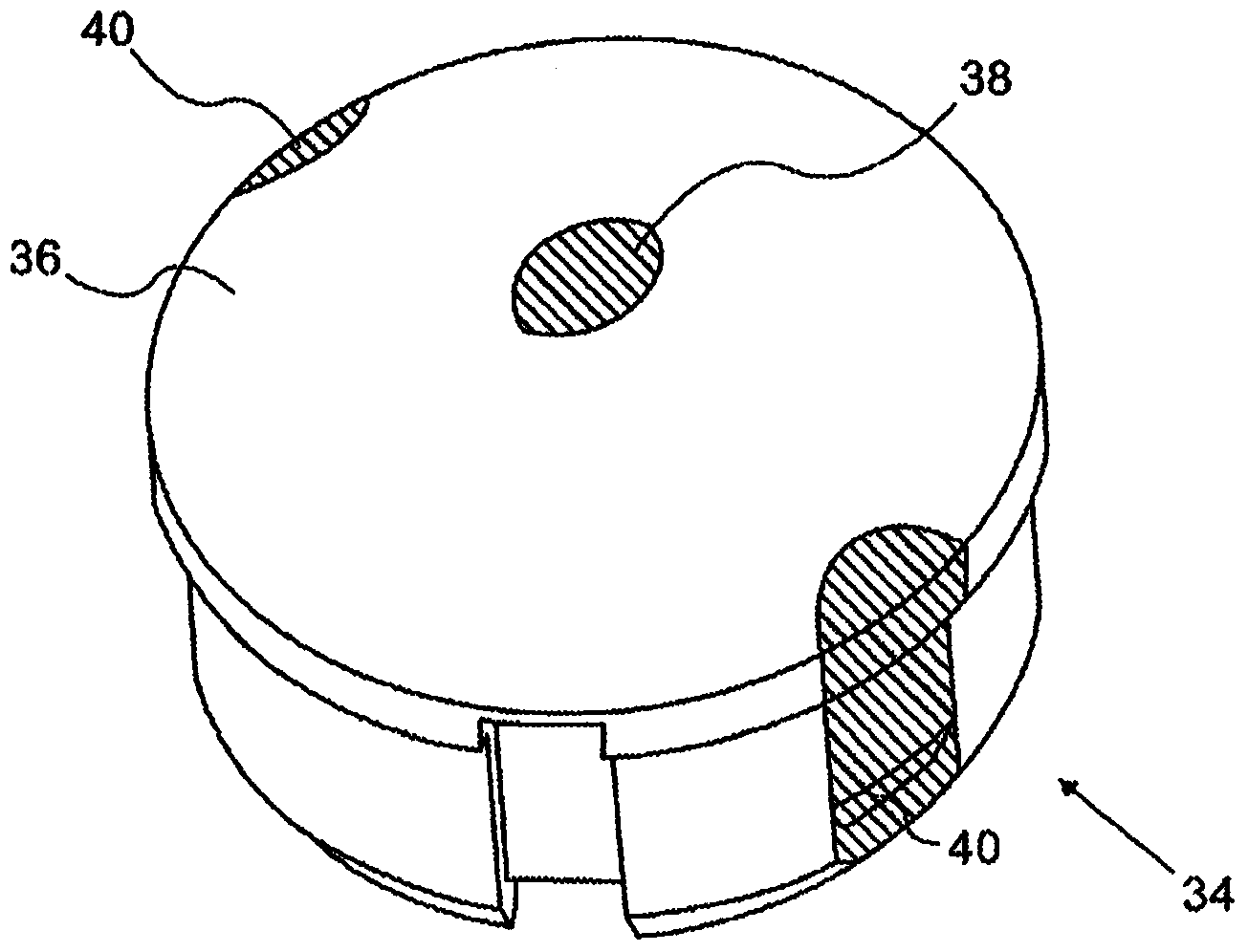
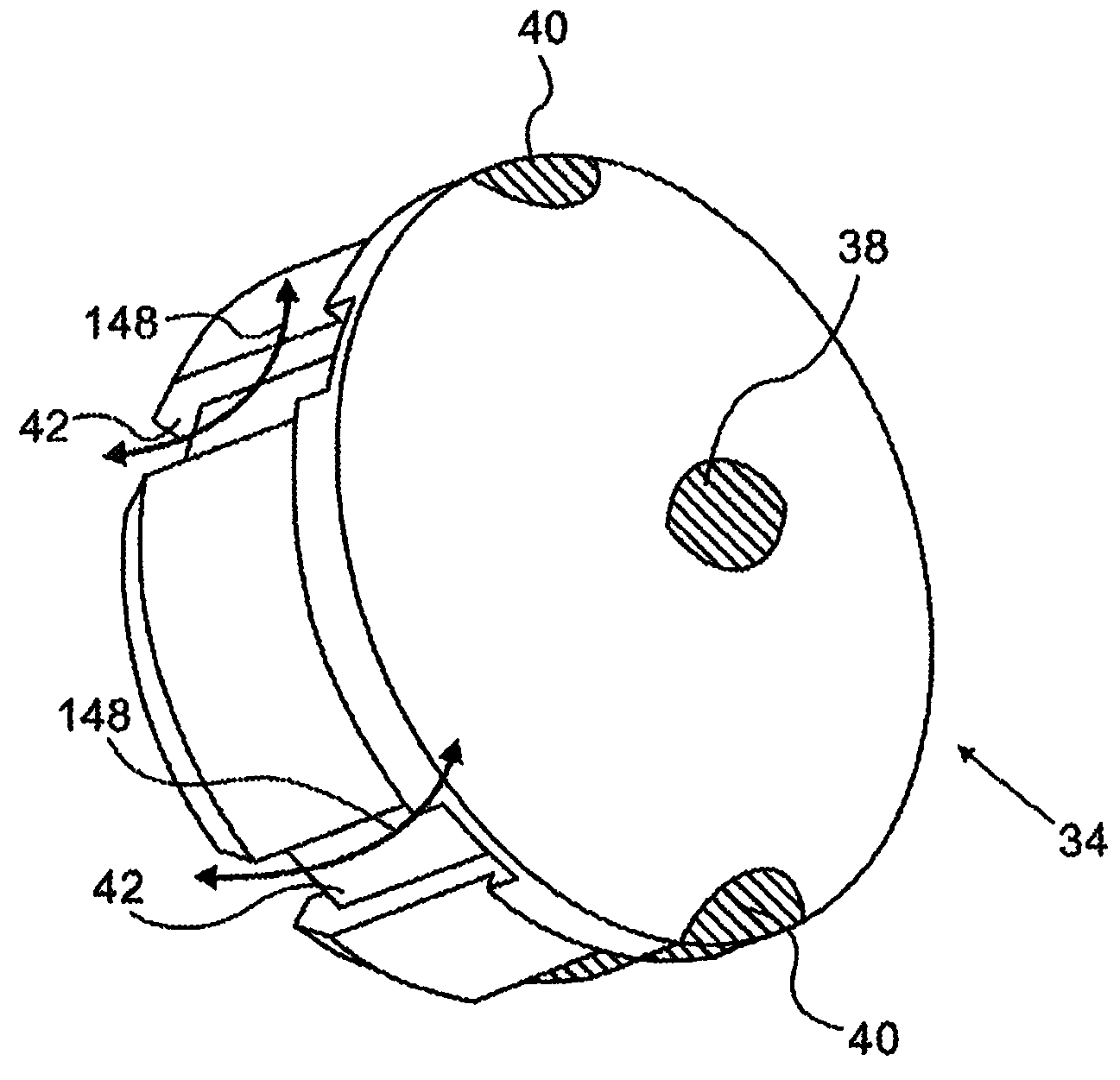
[0102] now refer to Figure 16 , Figure 16 is a side view of a bracket 154 for connection to a battery charging device in accordance with an embodiment of the present invention. This version is characterized by a circular ring 152 engaging the front end of the cigarette to keep the cigarette in contact with the holder 154 . Ring 152 should be made of a rubber material, such as silicone, in order to frictionally hold the front end of the cigarette inside holder 154 . The notch 156 retains the magnet 64 .

[0103] now refer to Figure 17 , Figure 17 is a top view of the bracket 154 with the ring 152 shown and the magnets 64, 66 in place.

[0104] now refer to Figure 18 , Figure 18 is a cross-sectional view of bracket 154 showing magnet 64 held in place by notch 156 .


PUM


Abstract

An electronic cigarette charging system includes a rechargeable electronic cigarette (173) having first and second electrical contacts (183), a cradle (175) that is connectable to a battery charger and a receiving element adapted to receive the end of the electronic cigarette (173). The receiving element has electrically conductive first and second contacts (181), which have first and second contact surfaces for contacting the first and second electrical con- tacts (183) of the electronic cigarette (175), respectively to thereby establish an electrical connection with the battery charger.

Description

[0001] Cross References to Related Applications [0002] This application claims the benefit of US Provisional Application No. 61 / 577,024, the entire contents of which are incorporated herein by reference. technical field [0003] The present invention relates to avoiding the use of tobacco products. More specifically, the present invention relates to a charger for battery-powered electronic cigarettes for inhibiting exposure to tobacco smoke. Background technique [0004] Smoking devices containing tobacco are known. For example, US Patent No. 7,726,320 (which is incorporated herein by reference) proposes a cigarette associated with an electrodynamic atomization generating device that acts as a cigarette holder. The smoking device has at least one form of tobacco. The smoking device also has a mouth end piece for use by the smoker to inhale tobacco constituents produced by the action of heat applied to the constituents of the cigarette. A representative smoking device ...

Claims


Application Information

Patent Timeline
Patent Type & Authority Applications(China)
IPC IPC(8): A24F47/00A24F40/10A24F40/40A24F40/50A24F40/90
CPCA24F47/008A24F40/10A24F40/50A24F40/90A24F40/40A24F40/46A61M15/06
Inventor 亚伦·阿里耶·威根斯博格什穆埃尔·加乌里耶罗夫塞米·卡普阿诺
Owner SIS RESOURCES LTD
Why Eureka
Try Eureka