Pipe cap for cantilever supporting device

A support device and pipe cap technology, which is applied to the field of high-speed electrified railway catenary, can solve the problems of inability to clean up dust pollutants on the surface of parts, decreased corrosion resistance, and sewage on the surface of the wrist arm support device, and achieves convenient manual disassembly and cleaning. contamination, improved safety and reliability, reduced cap shedding effect

Active Publication Date: 2014-11-12
中铁建电气化局集团轨道交通器材有限公司
View PDF7 Cites 2 Cited by
  • Summary
  • Abstract
  • Description
  • Claims
  • Application Information

AI Technical Summary

Problems solved by technology

High-speed electrified railway catenary often has the phenomenon that sewage and dust on the inner surface of the wrist arm support device cannot be removed
[0003] Pipe caps are usually used in conjunction with wrist and arm supports. In the high-speed rail catenary, most of them use soft PVC pipe caps. The assembly method is flexible connection, which is light in weight and easy to fall off.
Instead of using NA and NB caps, because the NA and NB caps are connected with the wrist arm support in an interference connection and cannot be dismantled, it is impossible to clean the dust and pollutants on the surface of the parts in the high-speed rail catenary site, and the corrosion resistance is reduced , bringing unnecessary hidden dangers to the catenary

Method used


Image

  • Pipe cap for cantilever supporting device
  • Pipe cap for cantilever supporting device
  • Pipe cap for cantilever supporting device

Examples


Embodiment Construction

[0014] The present invention will now be described in further detail with reference to the accompanying drawings. These drawings are all simplified schematic diagrams, and only illustrate the basic structure of the present invention in a schematic manner, so they only show the structures related to the present invention.

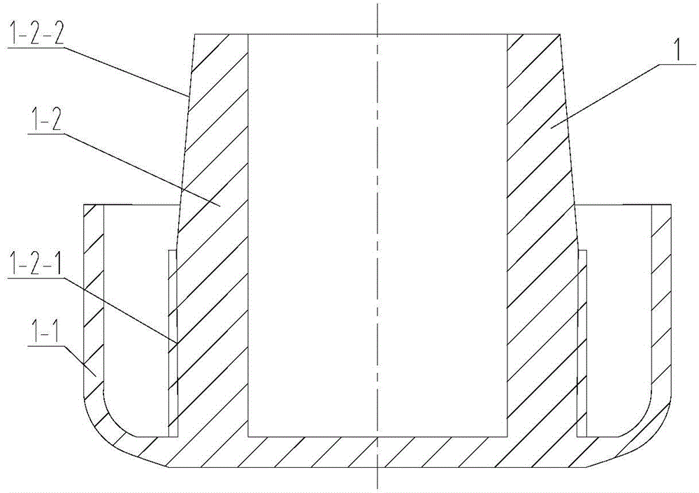
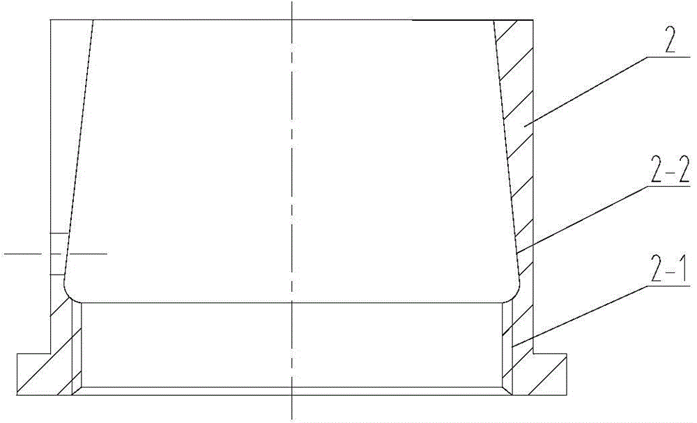
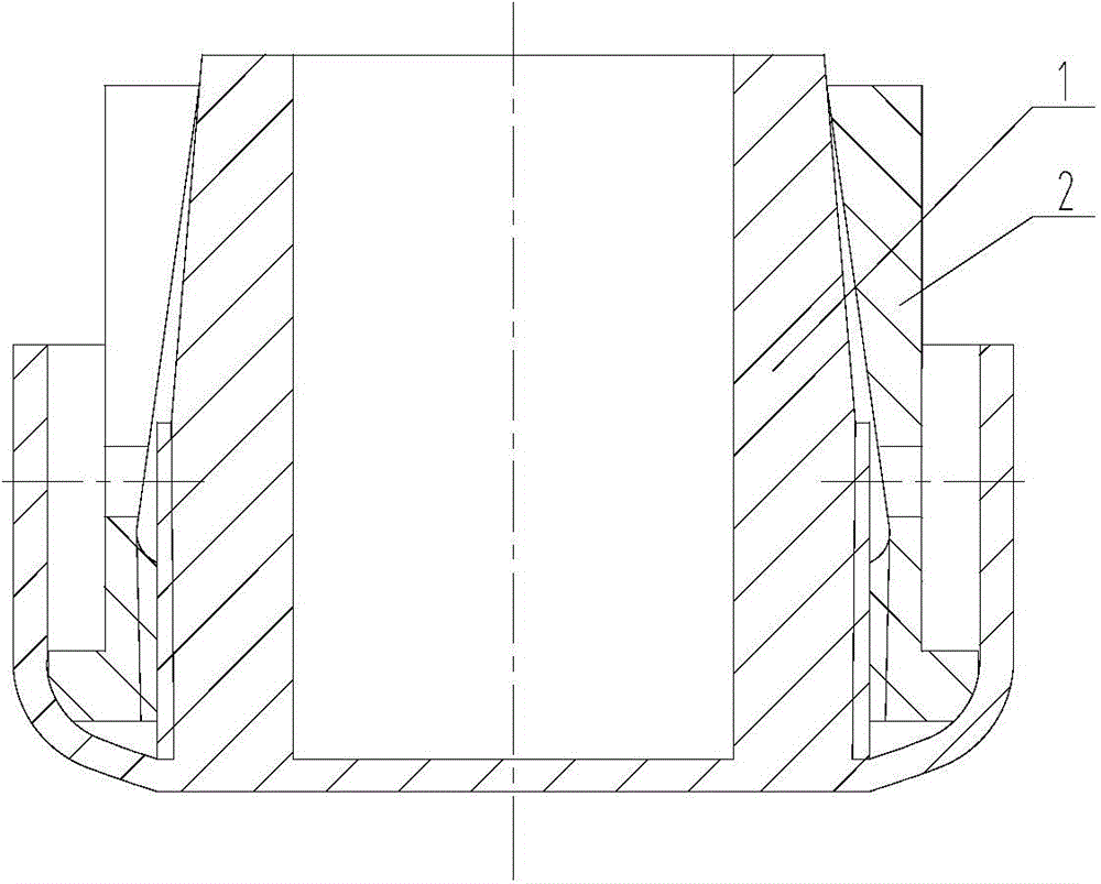
[0015] like figure 1 , figure 2 and image 3 The shown cap for the wrist arm support device has a cap body 1 made of nylon, the cap body 1 includes a U-shaped cap outer edge 1-1, and the middle position of the inner bottom wall of the cap outer edge 1-1 There is a U-shaped inner edge 1-2 of the cap with an opening extending upward and extending beyond the outer edge 1-1 of the cap, and the lower part of the outer side wall of the inner edge 1-2 of the cap is provided with an inner thread 1-2- 1. The upper part of the outer side wall of the inner edge 1-2 of the cap is provided with an inner wedge groove 1-2-2; The convex-shaped nylon bushing 2 at the ga...


PUM


Abstract

The invention relates to the technical field of an overhead contact system for a high-speed electrified railway, in particular to a pipe cap for a cantilever supporting device. The pipe cap for the cantilever supporting device is provided with a pipe cap body made of nylon. The pipe body comprises a U-shaped pipe cap outer edge. A U-shaped pipe cap inner edge is arranged in the middle of the inner bottom wall of the pipe cap outer edge, wherein an opening of the U-shaped pipe cap inner edge extends upwards, and the U-shaped pipe cap inner edge extends out of the pipe cap outer edge. Internal threads are arranged on the lower portion of the outer side wall of the pipe cap inner edge. An inner wedge groove is formed in the upper portion of the outer side wall of the pipe cap inner edge. The pipe cap is also provided with a T-shaped liner made of nylon, wherein the liner can be clamped in a gap between the pipe cap outer edge and the pipe cap inner edge in a wedged mode. The lower portion of the inner side wall of the liner is provided with external threads matched with the internal threads. The upper portion of the inner side wall of the liner is provided with an outer wedge groove matched with the inner wedge groove. The pipe cap for the cantilever supporting device can be assembled and disassembled manually on site and is convenient to operate, not prone to disengagement, and high in safety and reliability.

Description

technical field [0001] The invention relates to the technical field of high-speed electrified railway catenary, in particular to a pipe cap for a wrist arm support device. Background technique [0002] my country has a vast geography, large environmental differences, and increasingly serious environmental pollution. The high-speed electrified railway catenary often has the phenomenon that the sewage and dust on the inner surface of the wrist arm support device cannot be removed. [0003] The pipe cap is usually used in conjunction with the wrist arm support. In the high-speed rail catenary, most of the soft PVC pipe caps are used. The assembly method is movable connection, which is light in weight and easy to fall off. Instead of using NA and NB type caps, because the NA and NB type caps and the wrist arm support are fitted with an interference connection, the connection cannot be disassembled. In the high-speed rail catenary site, the dust contamination on the surface of t...

Claims


Application Information

Patent Timeline
IPC IPC(8): B60M1/20
Inventor 王旭陈可宁李东升蒋建州陈宁夫郑学广
Owner 中铁建电气化局集团轨道交通器材有限公司
Why Eureka
Try Eureka