
Inducing ventilation system of ship engine room

A technology of inducing ventilation and inducing fans, applied in the direction of hull ventilation/heating/cooling, ship components, ship construction, etc., can solve the problems of no cooling function in the ventilation system, uneven distribution of equipment, and many pipelines and cables, etc. Ventilation effect and ventilation efficiency, eliminating the need for duct arrangement, avoiding the effect of corrosion

Inactive Publication Date: 2014-11-12
JIANGSU JOSUN AIR CONDITIONER
View PDF6 Cites 10 Cited by
  • Summary
  • Abstract
  • Description
  • Claims
  • Application Information

AI Technical Summary

Problems solved by technology

The original ventilation system used in the ship’s engine room is to use a fan with a large pressure head, large air volume, and high power to exhaust the air through the air duct. Due to the large number of equipment in the engine room and not evenly distributed, there are structural girders and auxiliary beams on the top of the engine room, and the pipeline cables on the top There are so many lines, it is very difficult to arrange the air ducts, and it is impossible to arrange the air ducts in all positions, which is easy to form dead ends, and the entire ventilation system has no cooling function

Method used


Image

  • Inducing ventilation system of ship engine room

Examples


Embodiment Construction

[0014] The specific embodiments of the present invention will be described in further detail below with reference to the accompanying drawings:

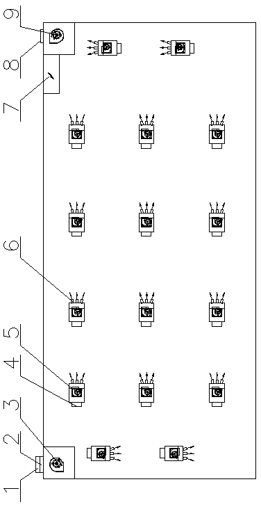
[0015] As shown in the figure, the ship’s engine room induction ventilation system includes a salt mist filter 1, a regulating air valve 2, a blower 3, an air heat exchanger 4, an induction fan 5, a jet nozzle 6, a centralized electrical control box 7, an air outlet 8 and exhaust Fan 9. The blower 3 is set on the top of the left corner of the cabin, the exhaust fan 9 is set on the top of the right corner of the cabin, and the outside of the cabin is provided with a salt mist filter 1 connected to the inlet of the blower 3. The salt mist filter An air volume regulating valve 2 is provided between 1 and the blower 3, and the air outlet 8 of the exhaust fan 9 extends out of the cabin; the cabin roof in the cabin is provided with a plurality of induction fans 5, and the air inlet of the induction fan 5 is provided In the air heat ex...


PUM


Abstract

The invention relates to an inducing ventilation system of a ship engine room. The inducing ventilation system comprises an air blower, an exhaust fan and an electrical control cabinet. The air blower and the exhaust fan are arranged at the tops of inner corners of the two sides of an engine room body respectively. The air blower and the exhaust fan are communicated with air inside and outside the ship engine room under the control of the electrical control cabinet. Inducing fans are arranged in the ship engine room, air inlets of the inducing fans are provided with air heat exchangers, and air outlets of the inducing fans are provided with jet flow nozzles in a scattered shape. The inducing fans are arrayed at intervals in a head and tail corresponding mode to form multiple circulation rings, wherein according to the circulation rings, air enters from the air blower, and air discharging is achieved through the exhaust fan. The air performs relaying according to a preset process through the inducing fans, so that an air flow pushing and pulling effect is achieved, a velocity field of air flowing is generated in the whole ship engine room, and ventilation is smoothly performed on the engine room. The arrayed inducing fans form relaying inducing air blowing, so that air pipes are omitted, space is saved, and cost is reduced.

Description

Technical field [0001] The invention relates to the field of ship ventilation equipment, in particular to an induction ventilation system for a ship engine room. Background technique [0002] With the global warming, coupled with the increase in equipment in the ship's engine room, the oil and gas and waste heat discharged by the equipment are directly discharged into the engine room, causing the air quality and temperature of the engine room to rise, affecting the health of the crew. The original ventilation system used in the ship's engine room uses a large-head, high-volume, and high-power fan to exhaust the air through a duct. Due to the large number of equipment in the engine room and not evenly distributed, there are structural beams and auxiliary beams on the top of the engine room, and pipeline cables on the top. There are so many lines, it is very difficult to arrange the air ducts, and it is impossible to arrange the air ducts in all positions, which is easy to form bl...

Claims


Application Information

Patent Timeline
Patent Type & Authority Applications(China)
IPC IPC(8): B63J2/06
Inventor 秦伯进陈兵周文兵敖晶申辉
Owner JIANGSU JOSUN AIR CONDITIONER
Learn More