Turbomachine stator internal shell with abradable material

一种涡轮机、内壳体的技术,应用在轴向涡轮机压缩机的压缩级,压缩级的密封领域,能够解决不可能明显改善密封等问题,达到制造成本降低、减小泄漏的效果

Active Publication Date: 2014-11-12
SAFRAN AERO BOOSTERS SA
View PDF10 Cites 14 Cited by
  • Summary
  • Abstract
  • Description
  • Claims
  • Application Information

AI Technical Summary

Problems solved by technology

However, it is not possible to significantly improve the seal between the inner casing and the rotor during steady state operation

Method used


Image

  • Turbomachine stator internal shell with abradable material
  • Turbomachine stator internal shell with abradable material
  • Turbomachine stator internal shell with abradable material

Examples


Embodiment Construction

[0053] In the following description, the terms inner and outer refer to a position relative to the axis of rotation of the axial turbine.

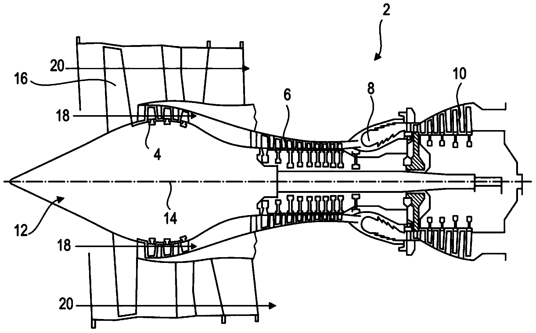
[0054] figure 1 An axial turbine is shown. In this example, it is a twin-flow turboprop 2 ; it could also be a turbojet 2 . The turboprop 2 comprises a first compression stage, a so-called low-pressure compressor 4 , a second compression stage, a so-called high-pressure compressor 6 , a combustion chamber 8 and one or more turbine stages 10 . In operation, the mechanical power of the turbine 10 is transmitted through the central shaft to the rotor 12 and drives the two compressors 4 and 6 . The reduction mechanism increases the rotational speed transmitted to the compressor. Alternatively, the different turbine stages may each be connected to the compressor stage by a concentric shaft. These concentric shafts include several rows of rotor blades associated with rows of stator blades. The rotation of the rotor about its axis of rotatio...


PUM


Abstract

The present application relates to a compression stage of a low-pressure compressor of an axial turbomachine, such as a turboprop. The stage includes a rotor with, on its outer surface, two lip seals, each forming a radial annular rib; and a stator which includes an annular row of stator blades extending substantially radially; and an inner shell whose radial cross section includes a central part connected to the inner tips of the blades, a lateral part extending from each side of the central part to one of the two lip seals, respectively, thus forming a rotor with the annular cavity. The shell and the rotor are configured so that the radial section of the annular cavity has a length L1 and a height H, the length L1 being greater than the height H, which initiates rotational movement of the air contained therein. The speed of the air reduces its pressure, which limits downstream to upstream leaks.

Description

technical field [0001] The invention relates to an axial turbine equipped with a compressor. More specifically, the present invention relates to compression stages for axial turbomachine compressors. More specifically, the present invention relates to sealing for compression stages of axial turbomachine compressors. Background technique [0002] Axial turbomachine compressors generally have several compression stages, each of which is formed by the combination of a row of rotor blades and a row of stator blades. In order to guide the flow axially in the compression stage, the compression stage has a coaxial housing. In particular, each row of stator blades is provided with an inner casing, which is fixed to the inner ends of the stator blades. Such an inner housing has an annular shape and surrounds the rotor. Some functional play where they join is part of the design. [0003] In operation, leakage may occur between the rotor and the inner housing due to this play. Th...

Claims


Application Information

Patent Timeline
Patent Type & Authority Applications(China)
IPC IPC(8): F04D29/16F04D29/52
CPCF01D9/041F01D25/24F04D29/161F01D11/001F04D29/102Y02T50/60F01D9/02
Inventor J-F.科特奎斯
Owner SAFRAN AERO BOOSTERS SA
Why Eureka
Try Eureka