Air supply system and method for industrial furnace

A technology of air supply system and industrial furnace, which is applied in the direction of combustion method, air supply adjustment, lighting and heating equipment, etc., which can solve the problems of large investment and high investment cost

A technology of air supply system and industrial furnace, which is applied in the direction of combustion method, air supply adjustment, lighting and heating equipment, etc., which can solve the problems of large investment and high investment cost

CN104141964BActive Publication Date: 2016-06-08上海金自天正信息技术有限公司

Image

  • Air supply system and method for industrial furnace
  • Air supply system and method for industrial furnace

Examples


Embodiment Construction

[0025] The present invention will be further described below in conjunction with the accompanying drawings and specific embodiments.

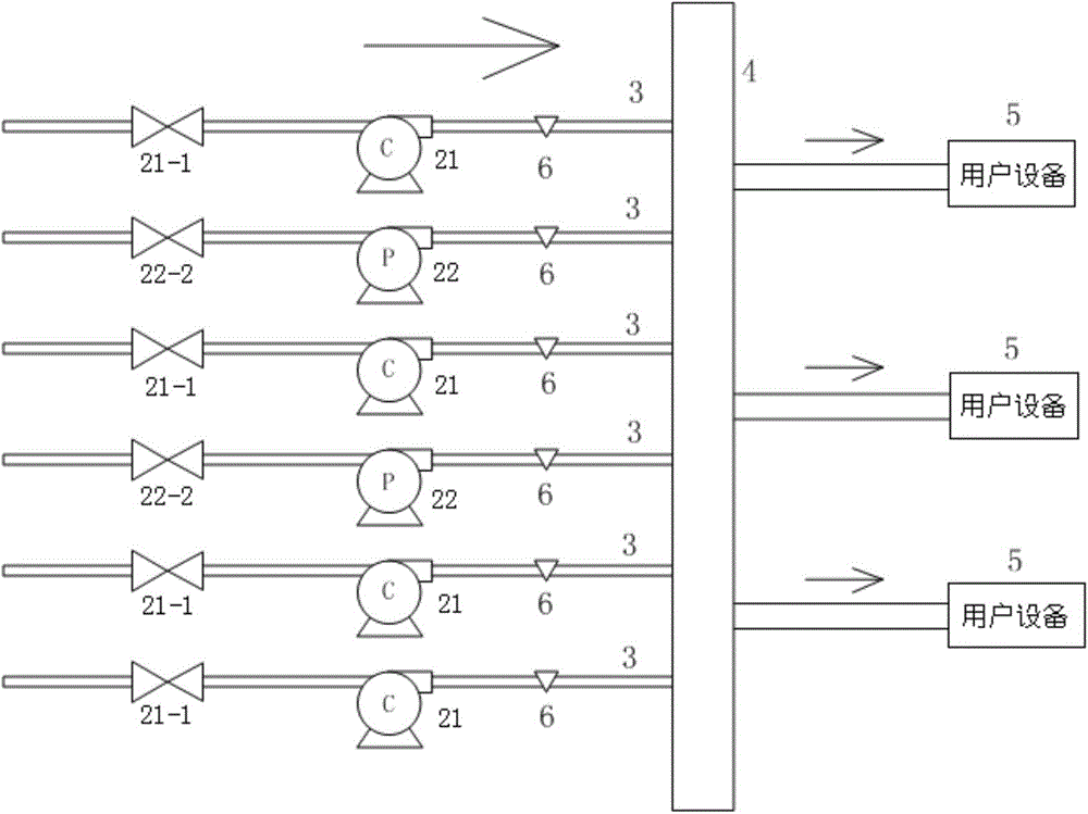
[0026] figure 1 It is a structural schematic diagram of the industrial furnace air supply system of the present invention.

[0027] Such as figure 1 As shown, the industrial furnace air supply system includes: constant speed fan 21, variable frequency fan 22, main pipe 4, branch pipe 3, user equipment 5, backstop baffle 6, air pressure sensor, controller and control panel. The user equipment is equipment such as a hot blast stove or a blast furnace that requires a fan to supply air.

[0028] The constant speed fan 21 has a constant speed fan damper 21-1, and the frequency conversion fan 22 has a frequency conversion fan damper 22-2.

[0029] The wind pressure sensor tests the actual wind pressure in the main pipeline. The controller compares the actual wind pressure measured by the wind pressure sensor with the set constant value of wind pr...


PUM


Abstract

The invention provides an air supply method of an industrial furnace. When air pressure is required to be increased, opening degrees of air doors of frequency conversion fans are increased; when the air pressure is required to be further increased, opening degrees of air doors of constant-speed fans are increased; when the air pressure is still required to be increased, working frequency of each frequency conversion fan is increased; when the air pressure is required to be decreased, the working frequency of each frequency conversion fan is decreased; when the air pressure is required to be further decreased, the opening degrees of the air doors of the frequency conversion fans are decreased; and when the air pressure is still required to be decreased, the opening degrees of the air doors of the constant-speed fans are decreased. The air supply method of the industrial furnace has the advantages as follows: for the fan units operating in an air door adjustment mode, only part of fans are subjected to frequency conversion renovation; and on the basis that the air pressure is stably adjusted through frequency conversion, the part of fans and other fans are controlled coordinately and combined to the overall fan unit network for stable operation.

Description

technical field [0001] The invention relates to an industrial furnace air supply system and a method thereof, which keep the pressure of the industrial furnace combustion-supporting hot air stable during the combustion process of the industrial furnace. Background technique [0002] At present, the air pressure automatic adjustment technology of domestic industrial furnace fan units is basically realized by adjusting the opening of each fan inlet damper, and controlling the output pressure parameters of the main pipe by changing the blade angle within a range of 90 degrees. The characteristic of this solution is that the investment cost is low, but the damper damper adjustment increases the pipeline resistance while throttling, and the motor needs to consume extra power to overcome the increased pipeline resistance, resulting in increased energy consumption. [0003] With the development of motor frequency conversion technology, some domestic single fans have begun to use fr...

Claims


Application Information

Patent Timeline
08 Jun 2016
Publication
CN104141964B
IPC
F23N3/00
Inventors
么淑华; 沈宏杰