Casting method for fusing metal gridding reinforcing body and a metal matrix

A metal grid and reinforcement technology, applied in the field of casting, can solve the problems of floating, sinking, agglomeration, uneven distribution and accurate positioning of reinforcements, poor consolidation strength of reinforcements, and high rejection rate of reinforcements. Economic and social benefits, firm consolidation and uniform distribution

Inactive Publication Date: 2014-11-19
吴建化
View PDF7 Cites 2 Cited by
  • Summary
  • Abstract
  • Description
  • Claims
  • Application Information

AI Technical Summary

Problems solved by technology

[0002] The traditional method of covering a layer of special-purpose reinforcements (such as wear-resistant and corrosion-resistant materials) on the surface of the casting or at a specific position is to place the reinforcement in the reserved cavity of the foam mold or powder-coat the reinforcement on the surface of the casting. The reserved position of the foam mold is pasted with adhesive. After the foam mold is solidified, it is directly molded and poured in the sand box. The whole system maintains a certain negative pressure. Under the high temperature of the molten metal, the foam mold gasifies and disappears, and the molten metal is filled Cavity, the reinforcing body is consolidated on the required position on the casting surface. This method is simple and low in cost, but it cannot solve the problems of floating, sinking, agglomeration, uneven distribution and accurate positioning of the reinforcing body. The scrap rate is high. Due to gravity or The effect of buoyancy, especially the sinking, floating, and accumulation of large particle reinforcements, cannot be solved, and the consolidation strength of reinforcements in castings is poor

Method used


Image

  • Casting method for fusing metal gridding reinforcing body and a metal matrix

Examples


Embodiment Construction

[0016] The present invention will be further described in detail below with reference to the embodiments of the present invention with accompanying drawings.

[0017] The invention provides a casting method for fusion of a metal grid reinforcement and a metal base, comprising the following steps:

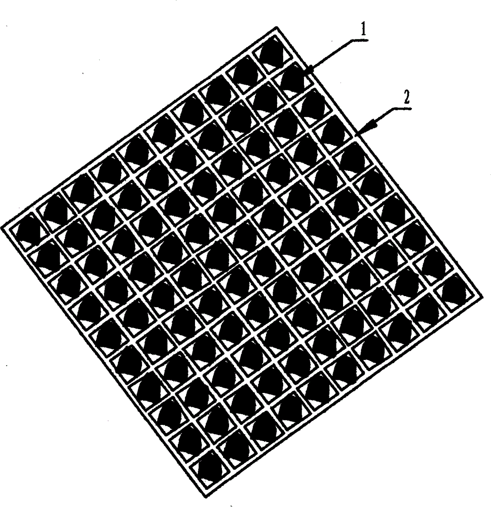
[0018] (1) Prepare the product mold, arrange the cemented carbide particles with reinforcement 1 as 3mm particles in the cavity of the metal grid 2, the metal grid 2 is a stamped part of 0.3mm brass sheet, and the cavity is a prismatic belt The thorn grid, the size is just enough to put 3mm particles, through the deformation of the mesh cavity and the thorn clamping of the cavity, it is like a diamond fixed on a ring, and the area size and shape of the metal grid 2 are consistent with the product;

[0019] (2) the metal grid 2 fixed with cemented carbide particles is installed in the corresponding position of the foam mold and fixed;

[0020] (3) Inject the foam material EPS pre-ex...


PUM


Abstract

The invention provides a casting method for fusing a metal gridding reinforcing body and a metal matrix. The casting method comprises the following steps of fixing reinforcing bodies (1) by using metal grids (2); mounting the reinforcing bodies (1) in corresponding positions of a foam mould; injecting pre-foamed foam beads in the foam mould to obtain a bright and clean foam mould with reinforcing body metal grids; accurately positioning the reinforcing bodies (1); uniformly coating foam mould clusters by using foam mold casting coatings; performing vibratory modeling on the foam mould clusters in a casting sand box; connecting a vacuumizing system to the casting sand box; pouring qualified smelted liquid metal on the foam mould; performing vacuumizing while pouring; and taking out the foam mould after cooling down the foam mold so as to obtain a casting on which the reinforcing bodies (1) are fused at accurate surface positions of the metal matrix. By the casting method, the reinforcing bodies (1) can be accurately positioned and uniformly distributed on the casting of the metal matrix; after the metal grids (2) and the metal matrix are fused, a transitional layer is formed; the reinforcing bodies (1) can be firmly fused with the metal matrix; the yield of products is improved; the cost is effectively reduced; and the quality of products is guaranteed.

Description

technical field [0001] The invention discloses a casting method for fusion of a metal grid reinforcement body and a metal base, in particular to a casting method for positioning a reinforcement body and metal base fusion by using a metal grid, and belongs to the field of casting. Background technique [0002] The traditional method of covering a layer of special-purpose reinforcements (such as wear-resistant and corrosion-resistant materials) on the surface of the casting or at a specific position is to place the reinforcement in the reserved cavity of the foam mold or powder-coat the reinforcement on the surface of the casting. The reserved position of the foam mold is pasted with adhesive. After the foam mold is solidified, it is directly molded and poured in the sand box. The whole system maintains a certain negative pressure. Under the high temperature of the molten metal, the foam mold gasifies and disappears, and the molten metal is filled Cavity, the reinforcing body ...

Claims


Application Information

Patent Timeline
Patent Type & Authority Applications(China)
IPC IPC(8): B22D19/14
Inventor 吴建化
Owner 吴建化
Why Eureka
Try Eureka