Method for manufacturing light reflecting material mold with microprism array structure

A technology of array structure and reflective material, applied in optics, optical components, instruments, etc., can solve the problems of single triangular pyramid structure, affecting the recognition performance of reflective materials, etc., and achieve the effect of good reflective effect.

Active Publication Date: 2014-11-19
ZHEJIANG DAOMING OPTOELECTRONICS TECH
View PDF6 Cites 15 Cited by
  • Summary
  • Abstract
  • Description
  • Claims
  • Application Information

AI Technical Summary

Problems solved by technology

However, when splicing according to the above method, the structure of the triangular pyramid that plays the role of the reflection core on the sub-board is single, and the distribution characteristics of the reflected light intensity of each triangular pyramid are consistent. Splicing, the distribution characteristics of the reflected light intensity of the microprism array structure on the large-sized metal nickel template formed are also consistent, and the distribution of reflected light intensity in different directions is different. When the light source has a certain divergence angle, in Different directions will show significantly different reflected light intensities, which will affect the recognition performance of the reflective material made from it

Method used


Image

  • Method for manufacturing light reflecting material mold with microprism array structure
  • Method for manufacturing light reflecting material mold with microprism array structure
  • Method for manufacturing light reflecting material mold with microprism array structure

Examples


Embodiment 1

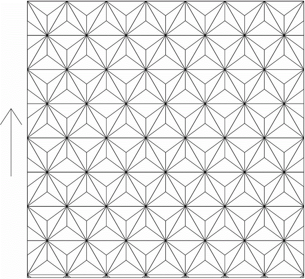
[0055] The manufacturing method of the reflective material mold with the microprism array structure comprises the following steps:

[0056] (a) Take a metal substrate, and engrave a raised microprism array structure on the metal substrate to form a metal template;

[0057] (b) Electroforming the metal template formed after the treatment in step (a) as a mother plate, using the mother plate as an electroforming cathode, copying a daughter plate made of nickel metal, and trimming the edges of the daughter plate ;

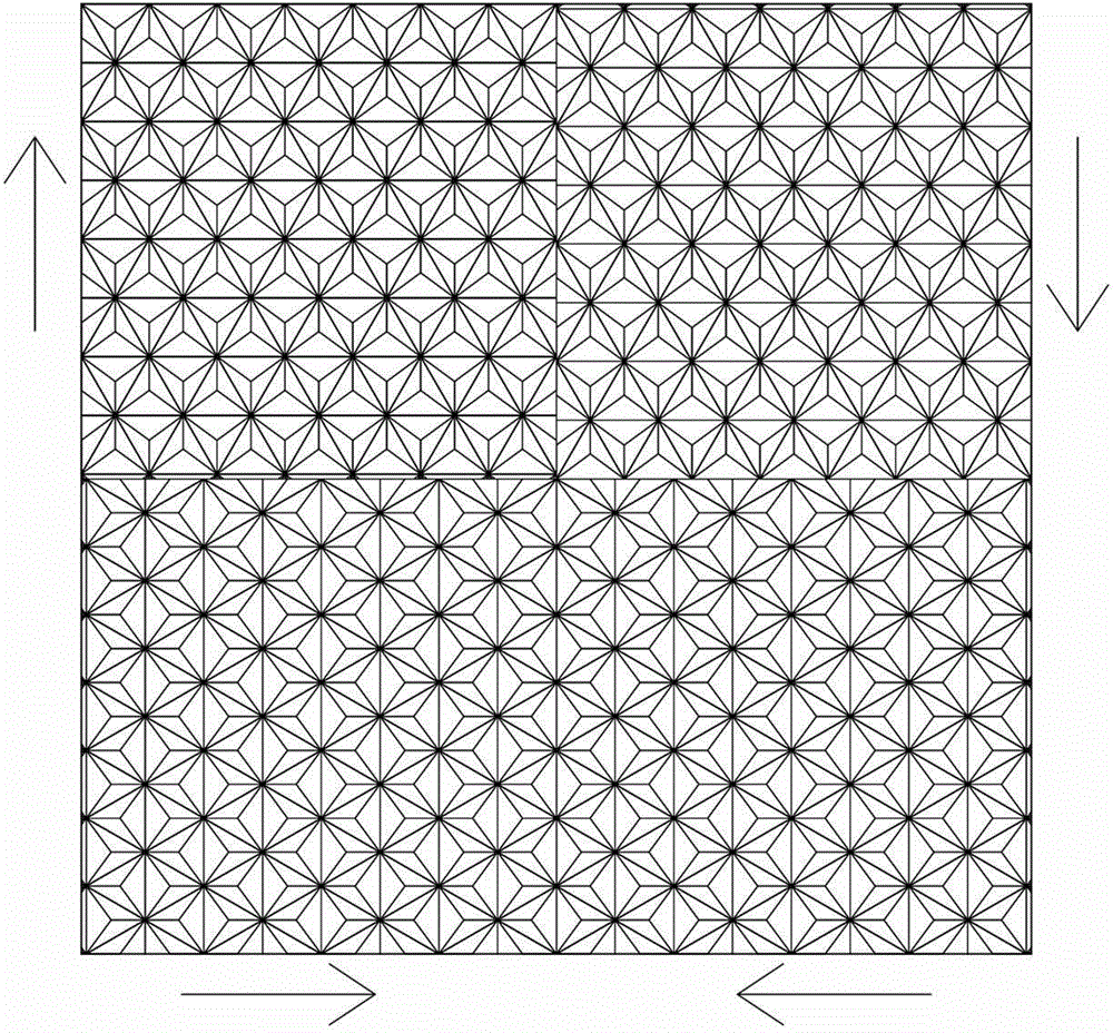
[0058] (c) cutting the sub-boards processed in step (b) to form multiple small boards;

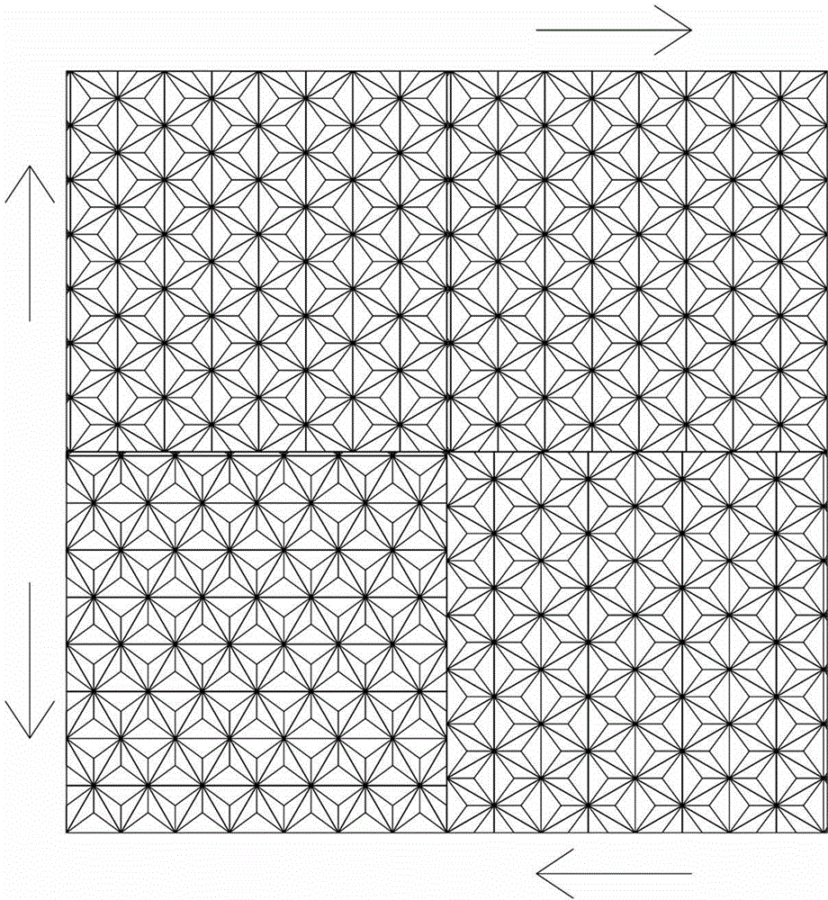
[0059] (d) rotating and splicing the small plates obtained in step (c) to form large plates;

[0060] (e) Using the large plate obtained in step (d) as the cathode of electroforming to form a plurality of large plates through multiple copies, and splicing the large plates one or more times to form a larger-sized metal nickel template, The production of the reflective material m...


PUM

PropertyMeasurementUnit
thicknessaaaaaaaaaa

Abstract

The invention relates to a method for manufacturing a light reflecting material mold with a microprism array structure. When the light reflecting material mold with the microprism array structure is manufactured through an existing method, copying and splicing are directly conducted on a metal mold plate, so that the microprism array structure of the light reflecting material mold embodies different reflected light intensities in different directions, and recognition performance of light reflecting material is influenced. The method includes the main steps of engraving a metal substrate to form the microprism array structure so as to form the metal mold plate, using the metal mold plate as a mother board to form a daughter board through copy, cutting the daughter board into a plurality of small boards, rotating the small boards, splicing the small boards into a large board, copying the large board multiple times to form a plurality of large board bodies, splicing the large board bodies one time or multiple times to form a mold plate in a larger size, and completing manufacturing of the light reflecting material mold with the microprism array structure. The light reflecting material mold manufactured through the method and provided with the microprism array structure has the same reflected light intensity distribution characteristic in different directions and has a better light reflecting effect.

Description

Technical field [0001] The present invention involves the method of making reflective material molds, and especially involves the method of reflective material mold with a micro -prism array structure. Background technique [0002] Due to its excellent reflex reflexity performance, reflective materials with micro -prism array structure are increasingly widely used in various road traffic safety facilities, vehicle passive safety protection devices, signs and personal safety protection products. [0003] The public date is CN101571606B on May 4, 2011, the invention patent application of the invention patent of "a large -sized micro -prism reflect material mold and preparation method" disclosed a combination of precision mechanical processing and casting process.The technical technical method to prepare a large -sized micro -prism reflective material mold, but this method includes two plating coverage, 2 power casts and several suppression.In the pressurized environment, the prism ...

Claims


Application Information

Patent Timeline
Patent Type & Authority Applications(China)
IPC IPC(8): B23P15/00G02B5/128
CPCB23P15/24
Inventor 王宏董云许德伟周金华郑魁
Owner ZHEJIANG DAOMING OPTOELECTRONICS TECH
Why Eureka
Try Eureka