Quick hole-milling positioning tool for strong-sucking type eccentric upper seal flange

A technology of positioning tooling and sealing on the heart, applied in the field of machining, can solve the problems of easy scar formation, long clamping time, and repeated milling machine changes, and achieves the effect of balanced internal and external forces, compact structure, and simplified structure.

Inactive Publication Date: 2014-11-19
四川富临集团成都机床有限责任公司
View PDF5 Cites 1 Cited by
  • Summary
  • Abstract
  • Description
  • Claims
  • Application Information

AI Technical Summary

Problems solved by technology

[0004] The purpose of the present invention is to provide a fast positioning tool for milling hole of strong suction eccentric upper head flange, which solves the problems of long clamping time, low efficiency, low yield and easy formation of scars in the current processing technology, and achieves The purpose of improving production efficiency and improving the qualified rate of finished products
The present invention is a core device proposed by the applicant based on a new process. The applicant found in many years of processing technology that the structure of the upper head flange is rather special, and the position of the groove on the end surface can be changed, but the groove The distance between a cylindrical blind hole at the end and the axis of the flange is fixed. In order to solve the problem of changing the milling machine many times in the existing processing technology, the applicant found after years of research that the blind hole at the end of the groove is the Datum, multiple positions can be processed at one time. First, a positioning plate is installed on the processing table of the milling machine through locking bolts. A set of arc-shaped side walls and eccentric positioning pins are arranged on the positioning plate. The side wall of the cylinder constitutes the outer circle of the cylinder, and the gap between the two arc-shaped side walls is formed. This gap plays an important role. After the sealing plate is put in, the sealing plate can be adjusted and rotated from the side of the gap. It is conducive to quick alignment and positioning. This outer circle is used as the installation reference of the processed sealing plate. When using it, firstly process the end face of the blank, and after processing a qualified end face, mill a groove on the other end face to process the processed One side of the groove is placed on the positioning plate downwards, and the sealing plate is rotated so that the positioning pin is inserted into the blind hole of the groove. At this time, the sealing plate no longer rotates. A conical surface, the conical surface plays a guiding role when putting in the sealing plate, which is convenient for quickly putting in the sealing plate, thereby increasing the speed of clamping; after positioning is completed, the solenoid valve is used as a switch to drive the cylinder, and the cylinder drives the pressure head to act On the sealing plate, press the sealing plate downward, and the sealing plate is fixed under the cooperation of the side wall, the positioning pin, and the pressure head. At this time, the axis hole, four through holes, and strip-shaped holes can be completed on a milling machine. Hole processing, in the processing process, the sealing plate is only clamped once, which improves the processing efficiency, and the position is fixed, it is easy to clamp, reduces the difficulty of alignment, avoids the inaccurate shape of the clamping, and at the same time a reference as the side The processing standards of the wall, four through holes, and strip holes maintain a high degree of uniformity, which improves the pass rate of finished products to more than 97%; the pressure head is made of wear-resistant rubber, and its bottom The upward depression forms a cavity, which forms the structure of a suction cup. When the cylinder drives the pressure head to move down and acts on the sealing plate, the air in the cavity is squeezed out, and the pressure of the air can be used to fix the pressure head and the sealing plate , and the large contact area can reduce the formation of the pattern on the surface of the workpiece; by setting the cooling pipe inside the support column, the cooling pipe is stored in the support column, which does not occupy space and has no messy wiring. The quick-connect plug is set on the top, and the external pipe can be used to use the cooling liquid in the process that needs to use the cooling liquid, but there is no cooling tube in the process that does not need the cooling liquid, which greatly reduces the space occupied by the cooling tube and simplifies the process. The structure achieves the purpose of simplicity and efficiency

Method used


Image

  • Quick hole-milling positioning tool for strong-sucking type eccentric upper seal flange
  • Quick hole-milling positioning tool for strong-sucking type eccentric upper seal flange

Examples


Embodiment

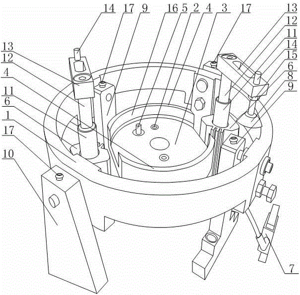
[0022] Such as figure 2As shown, the present invention is a fast positioning tool for milling hole of a strong suction type eccentric upper head flange, including a positioning ring 1, the positioning ring 1 is in the shape of a ring, and a pair of inner columns 9 and a positioning ring are installed on the inner side of the positioning ring 1. 1 is equipped with an outer column 10, the inner column 9 and the outer column 10 are evenly arranged on the positioning ring 1, and the connecting line of the inner column 9 and the connecting line of the outer column 10 are basically vertically distributed, and the positioning ring 1 passes through the inner column 9 Installed on the milling machine with the outer column 10, the inside of the inner column 9 and the outer column 10 are equipped with coolant pipes, and the inner column 9 and the outer column 10 are equipped with quick-connect plugs 17 communicated with the coolant pipes. The inner side of 1 is equipped with a cylinder ...


PUM


Abstract

The invention discloses a quick hole-milling positioning tool for a strong-sucking type eccentric upper seal flange. The quick hole-milling positioning tool comprises positioning rings and a positioning disc. The positioning disc is provided with a group of arc-shaped side walls and eccentric positioning pin, the arc-shaped side walls form an excircle, the inner surface of each arc-shaped side wall and each end plane are connected through an inclined plane, and the two inclined planes constitute a conical surface. The quick hole-milling positioning tool further comprises air cylinders, an electromagnetic valve and pressure heads made of wear-resistant rubber, and the bottom of each pressure head is upwardly recessed to form a cavity. The inclined planes constitute the conical surface functioning in guiding placing of a seal plate, the seal plate can be quickly and conveniently placed in, and clamping speed is increased. By the aid of air pressure, the pressure heads and the seal plate can be fixed, lines on the surfaces of workpieces can be reduced due to large contact area, and cooling pipes are arranged in support columns in a concealed manner, so that space is not occupied, the structure is simplified, and the pursuit of simplicity and high efficiency is realized.

Description

technical field [0001] The invention relates to a machining tool, in particular to a fast positioning tool for milling holes of a strong suction type eccentric upper head flange. Background technique [0002] The eccentric upper head flange is a special flange in the pipeline circulation industry, as attached figure 1 As shown, it includes a circular sealing plate 101, an axis hole 102 is opened on the axis of the circular sealing plate 101, and an axis sleeve 103 is installed on the axis hole 102, and a Four through-holes 106 distributed symmetrically around the axis are used to pass through and fix the measurement signal terminals, and arc-shaped strip holes 104 are arranged around the sealing plate 101 for the installation of seals An irregular groove 105 is recessed and formed on the sealing plate 101 for installing the signal measuring block, and its shape matches it. [0003] At present, the processing technology of the eccentric upper head flange is as follows: firs...

Claims


Application Information

Patent Timeline
Patent Type & Authority Applications(China)
IPC IPC(8): B23Q3/08B23Q11/12
CPCB23Q3/08B23Q2703/04
Inventor 彭小安李章文王亮
Owner 四川富临集团成都机床有限责任公司
Why Eureka
Try Eureka