Combined steel pipe pile for reducing wave force and seawater corrosion

A technology of seawater corrosion and steel pipe piles, which is applied in water conservancy projects, sea area projects, protection devices, etc., can solve the problems of weakening the bearing capacity of pile foundations, pile body fracture, and severe wave action, achieving significant economic benefits and reducing wave force , the effect of less steel consumption

Inactive Publication Date: 2014-11-19
HOHAI UNIV
View PDF6 Cites 3 Cited by
  • Summary
  • Abstract
  • Description
  • Claims
  • Application Information

AI Technical Summary

Problems solved by technology

However, the offshore sea conditions are complex and changeable, and the wave action is severe. There are some problems in the practical application of the steel pipe pile foundation: At present, most of the steel pipe piles used in offshore buildings are large-diameter steel pipe piles, and the large frontal area often makes the wave force The actual maximum bearing load of the steel pipe pile foundation, coupled with the orderly water flow vortex shedding caused by the circular section of the steel pipe pile, will cause the steel pipe pile foundation to swing strongly; the bending moment of the pile body caused by the wave force will The peak value is reached near the surface. Considering that the strength of ordinary steel pipe piles remains unchanged along the pile length, pile fractures are prone to occur near the seabed; in addition, seawater has a significant corrosion effect on steel, and the corrosion of steel pipe walls will gradually weaken. Bearing performance of pile foundation

Method used


Image

  • Combined steel pipe pile for reducing wave force and seawater corrosion
  • Combined steel pipe pile for reducing wave force and seawater corrosion
  • Combined steel pipe pile for reducing wave force and seawater corrosion

Examples


specific Embodiment

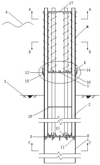
[0037] A project needs to set up pile foundations in an environment where the maximum wave height and water depth are 20m.

[0038]Large-diameter steel pipe piles 1 with an outer diameter of 2700mm and a wall thickness of 30mm are used. The top is 2m higher than the seabed, and the bottom is 60m below the seabed. The top of the large-diameter steel pipe pile 1 is welded with a reinforcing ring 13. The material of the reinforcing ring 13 is steel, with an inner diameter of 2700mm and an outer diameter of 3060mm. Sixteen ribs B15 are arranged at the junction of the outer wall of the pipe pile 1 . The rib plate B15 is made of a right-angled triangular steel plate with a thickness of 50mm, the side length of the side close to the large-diameter steel pipe pile 1 is 300mm, and the side length of the side close to the reinforcement ring 13 is 150mm.

[0039] The inside of the large-diameter steel pipe pile 1 is provided with an upper flange 8 and a lower flange 9 at 10 m from the s...


PUM


Abstract

A combined steel pipe pile for reducing wave force and seawater corrosion comprises a large-diameter steel pipe pile and a plurality of small-diameter steel pipe piles; the bottom of the large-diameter steel pipe pile is mounted below the seabed level; the top of the large-diameter steel pipe pile is above the seabed level; the small-diameter steel pipe piles are evenly and vertically welded in the large-diameter steel pipe pile; the top of each small-diameter steel pipe pile is above the sea level; the bottom of each small-diameter steel pipe pile is below the seabed level; the top end of the large-diameter steel pipe pile is abutted to a construction guard cylinder; each small-diameter steel pipe pile inside the construction guard cylinder is sleeved with a vortex remover; an anti-corrosion device is disposed between each two adjacent small-diameter steel pipe piles; an upper flange is horizontally welded at the bottom of each small-diameter steel pipe pile; the upper flanges are fixed to a lower flange welded on the inner wall of the large-diameter steel pipe pile. The combined steel pipe pile has the advantages that the acting force of small waves upon a pile foundation is effectively reduced, the capacity of the pile foundation to resist wave bending moment is enhanced, the pile foundation is less corroded by the pile foundation, and the pile foundation is more adaptive to severe sea conditions and safer.

Description

technical field [0001] The invention relates to a steel pipe composite pile for reducing wave force and seawater corrosion, and belongs to the field of steel pipe pile foundations for offshore construction. Background technique [0002] Steel pipe piles are widely used as the foundation of offshore buildings because of their light weight, good rigidity, convenient transportation, and easy driving, lengthening, and cutting construction. However, the offshore sea conditions are complex and changeable, and the wave action is severe. There are some problems in the practical application of the steel pipe pile foundation: At present, most of the steel pipe piles used in offshore buildings are large-diameter steel pipe piles, and the large frontal area often makes the wave force The actual maximum bearing load of the steel pipe pile foundation, coupled with the orderly water flow vortex shedding caused by the circular section of the steel pipe pile, will cause the steel pipe pile f...

Claims


Application Information

Patent Timeline
Patent Type & Authority Applications(China)
IPC IPC(8): E02D27/16E02D31/06E02B3/00
Inventor 黄挺郑金海
Owner HOHAI UNIV
Why Eureka
Try Eureka