Floor heating floor

A floor and floor heating technology, applied in the direction of floors, buildings, building structures, etc., can solve the problems of unsolved water and floor heating products, and achieve the effects of light weight, simple installation and low cost

Inactive Publication Date: 2014-11-19
江苏德威木业有限公司
View PDF8 Cites 5 Cited by
  • Summary
  • Abstract
  • Description
  • Claims
  • Application Information

AI Technical Summary

Problems solved by technology

Although a metal layer is used in this patent document, it does not solve the problems faced by water floor heating products

Method used


Image

  • Floor heating floor
  • Floor heating floor
  • Floor heating floor

Examples


Embodiment 1

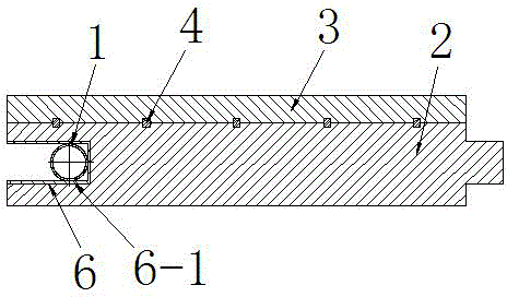
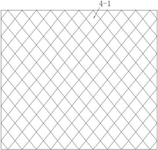
[0035] Embodiment 1: see attached figure 1 , attached figure 2, a floor heating floor, comprising a base material layer 2 at the bottom, a decorative panel layer 3 bonded to the top of the base material layer 2 by wood glue, and a metal mesh layer 4, the metal mesh layer 4 is placed between the base material layer 2 and the Between the decorative panel layers 3 and embedded in the connected base material layer 2 and the decorative panel layer 3 by hot pressing to form an integral structure, the thickness of the metal mesh layer 4 is less than or equal to the compression deformation of the connected base material layer and the decorative panel layer quantity. A tenon joint groove 6 is provided at the end of the floor, and a heat conduction surface 6-1 is provided on the inner wall of the tenon joint groove 6. The heat conduction surface 6-1 is made of a metal material aluminum alloy, and a hot water pipe is accommodated in the tenon joint groove 6-1. 1.

[0036] After hot r...

Embodiment 2

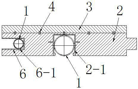
[0040] Embodiment 2: see attached figure 2 , attached image 3 , a floor heating floor, comprising a base material layer 2 arranged at the bottom, a decorative panel layer 3 bonded by wood glue on the upper part of the base material layer 2, and a metal mesh layer 4, between the adjacent base material layer 2 and the decorative panel A metal mesh layer 4 is arranged between the layers 3, and the metal mesh layer 4 located between the adjacent substrate layer 2 and the decorative panel layer 3 is embedded between the connected substrate layer 2 and the decorative panel layer 3 by hot pressing . The thickness of the metal mesh layer 4 is less than or equal to the compression deformation of the connected substrate layer and decorative panel layer. A tenon joint groove 6 is provided at the end of the floor, and a heat conduction surface 6-1 is provided on the inner wall of the tenon joint groove 6. The heat conduction surface 6-1 is made of a metal material aluminum alloy, and ...


PUM


Abstract

The invention relates to a floor heating floor which comprises a base material layer arranged at the bottom. A decoration panel layer is attached to the upper portion of the base material layer through adhesives. Metal mesh layers are further included, the metal mesh layers are arranged between the base material layer and the decoration panel layer and are embedded in the base material layer and the decoration panel layer which are connected through pressure rolling to form an overall structure. The metal mesh layers are continuously and evenly distributed in the embedded base material layer or/and embedded the decoration panel layer, and the thickness of the metal mesh layers is smaller than or equal to the compression deformation amount of the base material layer and the decoration panel layer which are connected. A joggling groove is formed in the end of the floor, a heat conduction face is arranged on the inner wall of the joggling groove, and a tubular or linear floor heating source is contained in the joggling groove. According to the floor heating floor, traditional materials are used for achieving the purpose of adjusting heat conduction coefficients, the floor and base materials can not be layered, using is stable, the heat conduction time is short, the heat conduction efficiency is high, energy consumption is low, and the cost is low.

Description

technical field [0001] The invention relates to a ground heating floor. Background technique [0002] With the continuous improvement of people's living standards, the demand for comfortable winter heating is also increasing, and the "hot water pipe network low-temperature ground radiation heating" technology is a heating method with relatively high sanitary conditions and comfort standards. It has been used for decades in China and is generally recognized by users. The "Design Standards for Energy Conservation of Residential Buildings" issued by the Ministry of Construction clearly stipulates that "when the indoor building area is greater than or equal to 80 square meters, it is advisable to use low-temperature ground radiation heating." [0003] Traditional water floor heating products still adopt the operation mode of on-site construction, that is, first lay insulation materials such as insulation boards or foamed cement on the ground, lay hot water pipe networks on it,...

Claims


Application Information

Patent Timeline
Patent Type & Authority Applications(China)
IPC IPC(8): E04F15/02
Inventor 葛林
Owner 江苏德威木业有限公司
Why Eureka
Try Eureka