Hydraulic damper

A hydraulic damper and oil technology, which is applied in the field of hydraulic dampers, can solve problems such as high manufacturing cost, difficult processing, and discontinuous damping force, so as to improve reliability and service life, reduce radial size and volume, and improve Effect of Response Sensitivity

Inactive Publication Date: 2014-11-19
ZHUZHOU TIMES EQUIP TECH
View PDF6 Cites 14 Cited by
  • Summary
  • Abstract
  • Description
  • Claims
  • Application Information

AI Technical Summary

Problems solved by technology

[0004] The main disadvantages of the above-mentioned hydraulic damper include: 1. Since the oil storage cylinder 10 is coaxially arranged with the oil cylinder body 1 and is sleeved outside the oil cylinder body 1, not only the hydraulic damper is bulky, complicated in structure, difficult to process and expensive to manufacture. High, and it is difficult to dissipate the heat generated by the hydraulic damper during the working process, which makes the temperature of the hydraulic damper extremely high during the working process. Excessively high temperature will not only cause the deterioration and aging of the hydraulic oil, but also affect the performance of the hydraulic damper. The working performance will also affect the sealing performance and service life of the seals; 2. The hydraulic oil in the oil storage cylinder 10 is in direct contact with the air, and the hydraulic oil is easy to emulsify under continuous or high-speed working conditions, resulting in The damping force is discontinuous, and problems such as external characteristic distortion, lost motion and noise are likely to occur during high-speed operation, which reduces the reliability and service life of the hydraulic damper; It is always in the oil to avoid the performance of the hydraulic damper from being sucked into the cylinder body 1 during the stretching stage. It is necessary to design the bases of the transverse damper and the vertical damper into different structures, resulting in the difference between the transverse damper and the vertical damper. Vertical dampers cannot be used universally

Method used


Image

  • Hydraulic damper
  • Hydraulic damper
  • Hydraulic damper

Examples


Embodiment Construction

[0023] The present invention will be further described in detail below in conjunction with the accompanying drawings and specific embodiments.

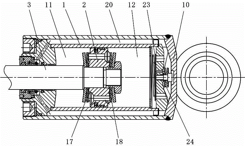
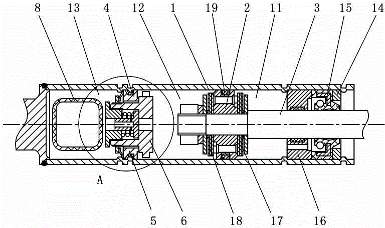
[0024] figure 2 and image 3 An embodiment of the hydraulic damper of the present invention is shown, the hydraulic damper includes a cylinder body 1, a piston 2 and a piston rod 3, the cylinder body 1 is provided with a working chamber, the piston 2 is arranged in the working chamber and The working chamber is divided into a first working chamber 11 and a second working chamber 12. One end of the piston rod 3 is installed on the piston 2, and the other end passes through the first working chamber 11 and is placed outside the cylinder body 1, and inside the cylinder body 1 is also There is a compensation chamber 13, which is located at the end of the second working chamber 12 away from the first working chamber 11, and a flow direction control assembly 4 is provided between the compensation chamber 13 and the second working chamber ...


PUM


Abstract

The invention discloses a hydraulic damper. The hydraulic damper comprises an oil cylinder barrel, a piston and a piston rod. A working cavity is arranged in the oil cylinder barrel. The piston is arranged in the working cavity. The working cavity is divided into a first working cavity and a second working cavity. One end of the piston rod is arranged on the piston. The other end of the piston rod penetrates through the first working cavity to be arranged outside the oil cylinder barrel. A compensation cavity is further arranged in the oil cylinder barrel. The compensation cavity is located at the end, far away from the first working cavity, of the second working cavity. A flow direction control assembly is arranged between the compensation cavity and the second working cavity. The hydraulic damper has the advantages of being simple in structure, small in size, high in reliability, long in service life, high in universality and the like.

Description

technical field [0001] The invention relates to a hydraulic damping device, in particular to a hydraulic damper. Background technique [0002] The hydraulic damper is made according to the principle of viscous resistance when the fluid passes through the orifice. It is a device that is sensitive to speed and can absorb and attenuate vibration. Because it can absorb and attenuate vibration and impact energy, reduce The dynamic response of components protects engineering structures and mechanical structures from damage caused by vibration and impact, and is widely used. [0003] Common hydraulic dampers in the prior art such as figure 1 As shown, the inner cavity of the cylinder body 1 is divided into the first working chamber 11 and the second working chamber 12 by the piston 2. In order to compensate or store the volume change of the hydraulic oil in the cylinder body 1 caused by the movement of the piston 2, it is necessary to An oil storage cylinder 10 is arranged outsid...

Claims


Application Information

Patent Timeline
Patent Type & Authority Applications(China)
IPC IPC(8): F16F9/36F16F9/32
Inventor 王凯平宋光伟殷盛福黎剑锋曾松林熊求颛陈永军陈健方照根
Owner ZHUZHOU TIMES EQUIP TECH
Why Eureka
Try Eureka