
Thermal management system and method for power battery pack

A power battery pack and thermal management system technology, applied in the thermal management system field of power battery packs, can solve problems such as difficult maintenance, low heating efficiency, and high cost, and achieve the effects of simple structure, convenient installation, and small heat loss

Inactive Publication Date: 2014-11-19
BEIJING ELECTRIC VEHICLE
View PDF4 Cites 39 Cited by
  • Summary
  • Abstract
  • Description
  • Claims
  • Application Information

AI Technical Summary

Problems solved by technology

[0004] Resistive heating sheet or PTC heating sheet heats the air and uses a fan to drive the air to flow, and forms convective heat exchange with the battery cell, or directly heats the battery cell by placing the heating element close to the battery cell. The heating efficiency of this method is very low and the temperature difference Larger, and will consume the energy of the power battery pack itself;
[0005] Forced air cooling is mainly to blow or inhale the air-conditioning air in the passenger compartment or the cold air in the environment into the battery compartment with a fan, and exhaust the hot air to the outside of the battery compartment to cool the batteries. This solution is inefficient. Moreover, the temperature difference is large, the protection level of the air inlet and outlet is low, and the airtight state of the battery compartment cannot be guaranteed
[0006] The liquid cooling solution uses heat conduction plates or other heat conduction materials to transfer the heat of the battery cell to the refrigerant, and the heat is taken away by the refrigerant. This method is costly, complex in structure, and difficult to maintain.

Method used


Image

  • Thermal management system and method for power battery pack

Examples


Embodiment Construction

[0036] The technical solutions of the present invention will be further described in detail below in conjunction with the accompanying drawings and embodiments.

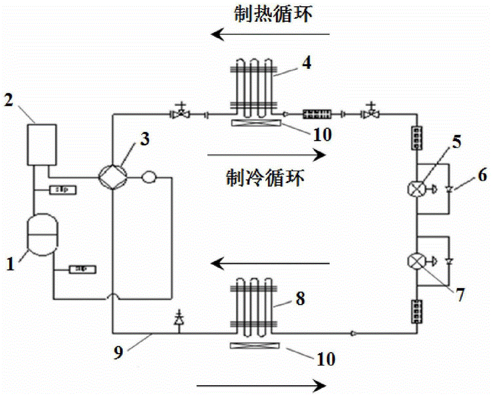
[0037] Heat pump technology is a new energy technology that obtains low-grade heat energy from natural air, water or soil, and provides high-grade heat energy through electricity. It has attracted much attention worldwide in recent years. coefficient), that is, the ratio of the heat transferred from a low-temperature object to a high-temperature object to the required power. The invention enables the power battery pack to work at a suitable ambient temperature by applying the heat pump technology to the thermal management of the power battery pack. The structure of the thermal management system of the power battery pack is as follows: figure 1 As shown, including heat pump device and thermal management unit, where:

[0038] The heat pump device includes a compressor 1, a closed loop formed by two of the four-way va...


PUM


Abstract

The invention provides a thermal management system and method for a power battery pack. The system comprises a heat pump device and a thermal management unit, wherein the heat pump device comprises a closed loop formed by a compressor, a four-way valve and a liquid storage tank, wherein the four-way valve is arranged between the compressor and the liquid storage tank; the thermal management unit comprises a heat exchange unit and a switching unit, the heat exchange unit comprises an out-car heat exchanger and an in-battery compartment heat exchanger, the switching unit comprises a heating expansion valve and a refrigeration expansion valve, and the four-way valve is connected with the out-car heat exchanger; the heating expansion valve, the refrigeration expansion valve and the in-battery compartment heat exchanger are connected with the out-car heat exchanger in sequence, and the in-battery compartment heat exchanger is further connected to the four-way valve to form a thermal management loop. According to the thermal management system and method for the power battery pack provided by the invention, the heat pump technology is applied to the thermal management of the power battery pack, so that the battery pack can work at the proper environmental temperature, and the unification of the heating and cooling thermal management can be realized.

Description

technical field [0001] The invention relates to a power battery pack of an electric vehicle, in particular to a thermal management system and method for a power battery pack. Background technique [0002] As the power source of electric vehicles, the power battery pack has a great influence on the temperature of the power battery pack. The available capacity of the power battery pack will be greatly lost in a low-temperature environment, and there are hidden dangers to its safety in a high-temperature environment. The alternating impact of high and low temperature seriously affects the service life of the power battery pack. Ensuring that the power battery pack works at a suitable temperature can optimize the performance, safety and service life of the battery. [0003] At present, the heating and cooling thermal management methods of power battery packs are completed through two sets of devices. The heating thermal management generally uses resistive heating sheets or PTC h...

Claims


Application Information

Patent Timeline
IPC IPC(8): H01M10/613H01M10/615H01M10/625H01M10/6569H01M10/635H01M10/6563H01M10/66
CPCY02E60/10
Inventor 俞会根翟文波
Owner BEIJING ELECTRIC VEHICLE
Learn More