Cable pulling device

A puller and cable technology, which is applied to the installation of cables, cable installation devices, electrical components, etc., can solve the problems of time-consuming, labor-intensive, low work efficiency, and inconvenient holding of the cable body, and achieve high operating efficiency and easy use. Convenient and fast, avoiding the effect of twisting and accumulating the cable body

Active Publication Date: 2014-11-19
STATE GRID CORP OF CHINA +1
View PDF6 Cites 9 Cited by
  • Summary
  • Abstract
  • Description
  • Claims
  • Application Information

AI Technical Summary

Problems solved by technology

[0003] The defects in the above-mentioned traditional operation method: on the one hand, the working efficiency of the method of manually grasping and pulling is low, especially the thick cable body is extremely inconvenient to hold, and there are few force points, which is time-consuming and labor-intensive; However, since the cable itself is already in the state of bending and stress when it is coiled on the cable reel, when the cable is pulled by human hands, it will often cause the cable body to twist along its circumference Considering that the manpower holding and pulling of the cable body is a continuous holding process, this leads to the gradual accumulation of the twisting degree of the above-mentioned cable body during the entire pulling process of the cable body, thus affecting the internal copper wires, etc. The fragile parts have adverse effects; in order to avoid the above phenomenon, the staff need to release the cable body with both hands after pulling a section of cable and wait for the deformation to recover before dragging, which will inevitably reduce the actual work efficiency
[0004] Based on the above reasons, some manufacturers have also considered using some machinery such as clamping rollers instead of manpower to hold and pull cables for laying. However, regardless of the size of the mechanical equipment and the inconvenience of transportation and installation, other When the equipment is pulling the cable, the cable body twisting phenomenon is often more significant than that of traditional manual construction. This is because the machine pulling is more consistent than manpower, which leads to a more accumulated twisting degree of the cable body. Fast, under the long-term accumulation of the above-mentioned deformation of the cable body, the cable body tends to tear or even break faster, which not only increases the actual construction cost, but also brings great trouble to the on-site staff.

Method used


Image

  • Cable pulling device
  • Cable pulling device
  • Cable pulling device

Examples


Embodiment Construction

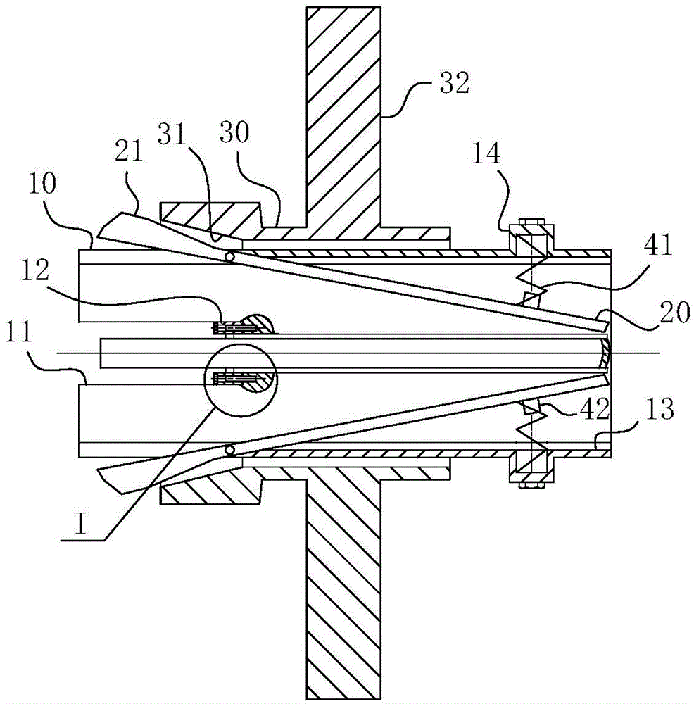
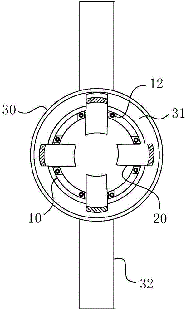
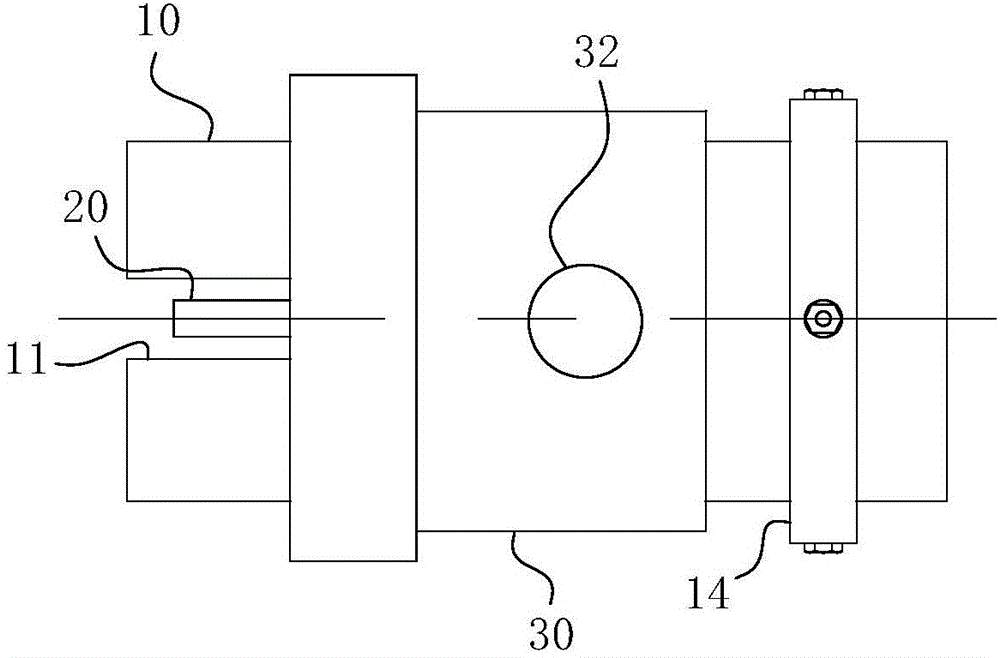
[0038] combine here Figure 1-7 The specific implementation structure and work flow of the present invention are further described as follows:

[0039] For ease of understanding, the arc side of the clamp rod 20 facing the axis of the collar portion 10 is used as the inner wall, and the arc side facing away from the axis of the collar portion 10 is also the outer wall; at the same time, the present invention The action direction of the cable body inserted into the cable a is its forward action direction, and the pulling direction of the cable body relative to the cable a is its reverse backward action direction.

[0040] Concrete implementation structure of the present invention, refer to Figure 1-4 As shown, it includes a collar part 10 for being directly sleeved on the cable body of the cable a. The collar part 10 is provided with a tapered clamping tooth formed by a clamp rod 20 around the axis of the collar part 10 (that is, a clip The shape of the conical clamping teet...


PUM


Abstract

The invention belongs to the field of cable installation matching equipment and particularly relates to a cable pulling device. The cable pulling device comprises an annular sleeving part and a clamping part. The profile of the clamping part is a cone cage-shaped fence. Each clamp rod on the clamping part can synchronously leave or approach the axis of the annular sleeving part along the radial direction of the annular sleeving part in a reciprocating manner. The minimal inner diameter of the clamping part is smaller than the outer diameter of a to-be-pulled cable body, and the maximal inner diameter is larger than or equal to the outer diameter of the to-be-pulled cable body. The outer wall of the annular sleeving part is provided with a handle part. A large-diameter port of the annular sleeving part, at the clamping part, is provided with notch grooves. The profile of each clamp rod is straight, each clamp rod is positioned in one notch groove, and a body of each clamp rod is hinged to groove walls at two sides. The axis of a hinged shaft formed by each clamp rod and one notch groove is vertical to the axis of the annular sleeving part. The cable pulling device also comprises an elastic reset unit. The cable pulling device is convenient to use and high in operational efficiency, and can effectively solve a problem that distortion of a cable body is accumulated when a traditional cable is pulled.

Description

technical field [0001] The invention belongs to the field of supporting equipment for cable installation, and in particular relates to a cable puller. Background technique [0002] With the continuous development of my country's electric power industry, the use of cables and other cables has become more and more popular in real life. At present, for the installation and construction of cables, most of them still adhere to the traditional installation measures, that is, after the cable reel is unloaded to the construction point, it is first installed on the rotating bracket, and then the cable body is pulled by manpower. Thereby, the rotation of the cable reel relative to the rotating bracket is realized, thereby achieving the purpose of pulling out the cable and installing it later. [0003] The defects in the above-mentioned traditional operation method: on the one hand, the working efficiency of the method of manually grasping and pulling is low, especially the thick cabl...

Claims


Application Information

Patent Timeline
Patent Type & Authority Applications(China)
IPC IPC(8): H02G1/00
Inventor 李友明
Owner STATE GRID CORP OF CHINA
Why Eureka
Try Eureka