
A motor driver protection circuit and protection method

A motor driver and protection circuit technology, applied in emergency protection circuit devices, electrical components, etc., can solve problems such as incomplete circuits and protection methods, reduce the risk of device overvoltage damage, delay charging time, and reduce bus voltage. Effect

Active Publication Date: 2017-03-08
成都乐创自动化技术股份有限公司
View PDF6 Cites 0 Cited by
  • Summary
  • Abstract
  • Description
  • Claims
  • Application Information

AI Technical Summary

Problems solved by technology

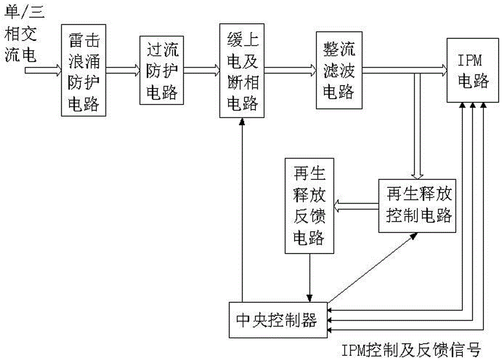
[0007] The purpose of the present invention is to solve the incompleteness of the existing technology due to the incompleteness of the design circuit and the protection method, that is, when there is a problem with the device of the release circuit, the system cannot know in advance, and provide a motor driver protection circuit and protection method. Based on the regenerative release control circuit, this circuit designs a regenerative release feedback circuit that can judge whether the driver has abnormal release in advance according to the signal state of the regenerative release control circuit. Actions, allowing customers to deal with and eliminate hidden dangers in a timely manner to avoid accidents or additional losses. In the application of protection methods, the protection method combined with regeneration and release feedback is adopted to timely judge that the regeneration and release action is actually effective, and when the circuit is abnormal detection and take corresponding protective actions in advance

Method used


Image

  • A motor driver protection circuit and protection method
  • A motor driver protection circuit and protection method

Examples


Embodiment 1

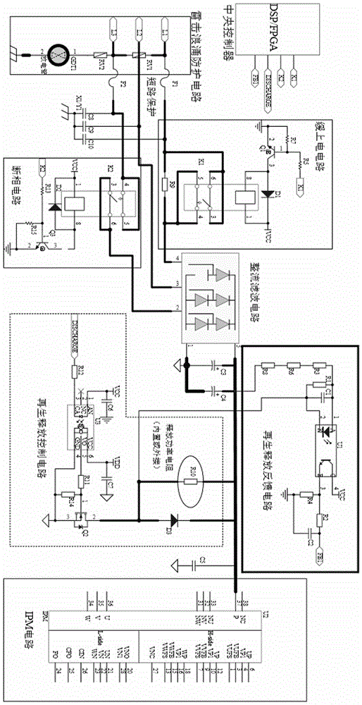
[0030] A motor driver protection circuit such as figure 1 , figure 2 As shown, it includes lightning surge protection circuit, overcurrent protection circuit, slow power-on and phase failure circuit, rectification filter circuit, IPM circuit, regeneration release control circuit, regeneration release feedback circuit and central controller, and the rectification filter circuit is connected to The regeneration release control circuit, the IPM circuit is connected to the regeneration release control circuit, the regeneration release control circuit is connected to the regeneration release feedback circuit, and the central controller is respectively connected to the IPM circuit, the regeneration release control circuit and the regeneration release feedback circuit.

[0031]The main working principle: the signal of the regeneration release control circuit is sampled back through the detection circuit, so that the system can know whether the release is effective. At the same time,...

Embodiment 2

[0033] This embodiment is further optimized on the basis of the above embodiments, such as figure 2 As shown, the regenerative release feedback circuit includes an RC anti-jamming circuit composed of resistors and capacitors connected in parallel, an optocoupler, a current limiting resistor, an RC series filter circuit, and a pull-down resistor R4; the 2 pins of the optocoupler input end are connected to the RC anti-jamming circuit respectively. One end of the parallel connection of the circuit and the drain of the MOS tube of the regeneration release control circuit, the first pin of the optocoupler input terminal is connected to the other end of the parallel connection of the RC anti-interference circuit, and the first pin of the optocoupler input terminal is connected to the bus through a current limiting resistor; The 4 pins of the optocoupler output end are connected to VCC, the 3 pins of the optocoupler output end are connected in series with the pull-down resistor R4 to...

Embodiment 3

[0037] This embodiment is further optimized on the basis of Embodiment 2. The current limiting resistor is a potentiometer, one fixed end of the potentiometer is connected to pin 1 of the input terminal of the optocoupler, and the other fixed end of the potentiometer is connected to the bus bar.


PUM


Abstract

The invention discloses a motor driver protection circuit and a motor driver protection method. The motor driver protection circuit comprises a lightning surge protection circuit, an over-current protection circuit, a slow powering-on and open-phase circuit, a rectifying and filtering circuit, an IPM circuit, a regeneration release control circuit, a regeneration release feedback circuit and a central controller. The protection method includes lightning surge protection, over-current protection, slow start and open-phase protection, regeneration release control protection, and release detection. The regeneration release feedback circuit which can judge whether a driver has abnormal release in advance according to the signal state of the regeneration release control circuit is designed. When the driver carries out self-check and finds a problem, warning can be issued in advance and corresponding protection actions can be taken, so that customers can handle the problem timely and eliminate hidden dangers so as to avoid accidents or additional loss. The protection method is combined with regeneration release feedback and is practical and effective in timely judgment of regeneration release actions, detection can be carried out in case of circuit abnormality, and corresponding protection actions can be taken in advance.

Description

technical field [0001] The invention relates to the field of drive control, in particular to a motor driver protection circuit and protection method. Background technique [0002] Servo drives (servo drives), also known as "servo controllers" and "servo amplifiers", are a kind of controller used to control servo motors. Its function is similar to that of frequency converters on ordinary AC motors. It is mainly used in high-precision positioning systems. Generally, the servo motor is controlled by three methods of position, speed and torque to achieve high-precision positioning of the transmission system. It is currently a high-end product of transmission technology. [0003] The existing mainstream servo drives all use digital signal processors (DSP or FPGA) as the control core, which can realize relatively complex control algorithms and realize digitization, networking and intelligence. Power devices generally adopt the drive circuit designed with the intelligent power mo...

Claims


Application Information

Patent Timeline
Patent Type & Authority Patents(China)
IPC IPC(8): H02H7/08
Inventor 宋莹君周莹杜嘉
Owner 成都乐创自动化技术股份有限公司
Learn More