Range finder pulse interference suppression method combining orthogonal projection and circular beam forming

A beamforming and orthogonal projection technology, applied in the transmitter/receiver shaping network, baseband system components, multi-frequency code system, etc. Suppression, the position of the pulse interference signal is not easy to determine, etc.

Active Publication Date: 2014-11-19
CIVIL AVIATION UNIV OF CHINA
View PDF7 Cites 10 Cited by
  • Summary
  • Abstract
  • Description
  • Claims
  • Application Information

AI Technical Summary

Problems solved by technology

In practical application, this method has the following two problems: the position where the pulse interference signal appears is not easy to determine, and the ICI interference is caused after the pulse is extinguished
There are also two problems in the pulse clipping method: the pulse clipping value is not easy to determine, and the signal still has pulse interference after pulse clipping
However, in the L-band digital aviation communication system 1 (L-DACS1), the pulse interference generated by the range finder is strongly correlated pulse interference, so the compressive sensing method is difficult to be directly applied to the pulse interference suppression of the OFDM system range finder

Method used


Image

  • Range finder pulse interference suppression method combining orthogonal projection and circular beam forming
  • Range finder pulse interference suppression method combining orthogonal projection and circular beam forming
  • Range finder pulse interference suppression method combining orthogonal projection and circular beam forming

Examples


Embodiment Construction

[0068]The method for suppressing pulse interference of a rangefinder combined with orthogonal projection and cyclic beamforming according to the present invention will be described in detail below with reference to the embodiments and the accompanying drawings.

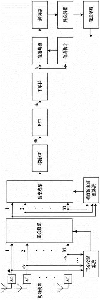
[0069] In order to solve the problem that the L-band digital aeronautical communication system 1 (L-DACS1) is deployed in the L-band in an embedded manner, the strong pulse of the rangefinder interferes with the OFDM receiver of the L-band digital aeronautical communication system. The invention proposes a rangefinder pulse interference suppression method combining orthogonal projection and cyclic beamforming. This method utilizes the aircraft in the flight stage of the route, and the aviation channel mainly propagates in the direct channel and scattering mode, and the direct path and scattered path radio waves are incident Due to the large angle expansion characteristics, a rangefinder pulse interference suppression m...


PUM


Abstract

The invention discloses a range finder pulse interference suppression method combining orthogonal projection and circular beam forming. The method comprises the following steps: converting radio-frequency signals from an array antenna into analog baseband signals through a radio-frequency front end, converting the analog baseband signals into digital baseband signals through A / D (Analog to Digital) conversion, computing a plurality of digital baseband signals through an orthogonal projection algorithm to obtain a projection matrix of an interference signal orthogonal complementary space, applying the projection matrix to a receiving signal vector to eliminate interference of a range finder pulse signal, further acquiring the beam forming weight vector of the array antenna through a circular beam forming method, performing beam forming on the signal vector of which pulse interference is eliminated, and extracting an OFDM (Orthogonal Frequency Division Multiplexing) direct path signal; and removing a cyclic prefix, converting the OFDM direct path signal into a frequency domain signal through an FFT (Fast Fourier Transform) algorithm, further performing four-time frequency domain down sampling, estimating channel characteristics through a channel, performing channel balance through a balancer, and processing through a demodulator, a deinterleaver and a decoder in sequence to obtain the estimated value of a transmission bit sequence. By adopting the method, the interference of pulse and scattered multipath signals of a range finder can be overcome effectively.

Description

technical field [0001] The invention relates to a method for suppressing pulse interference of a range finder. In particular, it relates to a pulse interference suppression method for a rangefinder combined with orthogonal projection and cyclic beamforming. Background technique [0002] In order to ensure the safe, reliable and efficient operation of the new generation air traffic management system of civil aviation, the International Civil Aviation Organization (ICAO) proposed two candidate technical solutions for ground-air data links: L-band Digital Aviation Communication System 1 (L-DACS1) and L-band Digital Aeronautical Communication System 2 (L-DACS2), in which, the L-DACS1 system adopts a multi-carrier Orthogonal Frequency Division Multiplexing (OFDM) transmission scheme, and the L-DACS2 system adopts a single-carrier Gaussian Minimum Frequency Shift Keying (GMSK) transmission scheme . Compared with the L-DACS2 system, the L-DACS1 system has the advantages of higher...

Claims


Application Information

Patent Timeline
Patent Type & Authority Applications(China)
IPC IPC(8): H04L25/03H04L27/26
Inventor 刘海涛刘亚洲成玮张学军
Owner CIVIL AVIATION UNIV OF CHINA
Why Eureka
Try Eureka