Fixtures for processing glass mold dies

A technology for processing glass and die, applied in manufacturing tools, metal processing equipment, metal processing mechanical parts, etc., can solve the problems of complex structure, clamping failure, troublesome production and assembly, and achieve the effect of simple overall structure

Active Publication Date: 2016-04-06
CHANGSHU JIANHUA MOLD TECH
View PDF15 Cites 6 Cited by
  • Summary
  • Abstract
  • Description
  • Claims
  • Application Information

AI Technical Summary

Problems solved by technology

[0007] However, the technical solution recommended by the aforementioned CN103056695A is deficient and eliminated by the "fixture structure for processing the mating surface of the glass mold blank" provided by the invention patent application publication number CN103252670A. For details, please refer to paragraphs 0008 and 0021 of the description of the patent application
Clamping the two half-mold blanks of a pair of molds with the clamping surface facing upwards and using a CNC milling machine to perform milling on the clamping surface and the cavity is the contribution of this patent application, but for the clamping of the die There is no technical enlightenment that can be used for reference. For example, when it is necessary to mill the end face of the half-die blank to process the positioning reference position (referred to as the reference position), there are two clamping points for the clamp on the half-die blank: one is the outer circle, The second is the clamping surface, that is to say, the outer arc surface of the die half blank and the clamping surface of the die half blank are clamped by the clamp at the same time, so this clamping method will be subjected to a pair of The interference of the support module (CN103252670A called the first support module and the second support module) caused the clamping failure
In addition, the structure of the CN103252670A is relatively complicated, and it is troublesome to manufacture, assemble and use

Method used


Image

  • Fixtures for processing glass mold dies
  • Fixtures for processing glass mold dies

Examples


Embodiment Construction

[0023] In order to enable the examiners of the patent office, especially the public, to understand the technical essence and beneficial effects of the present invention more clearly, the applicant will describe in detail the following in the form of examples, but none of the descriptions to the examples is an explanation of the solutions of the present invention. Any equivalent transformation made according to the concept of the present invention which is merely formal but not substantive shall be regarded as the scope of the technical solution of the present invention.

[0024] In the following descriptions, all concepts involving up, down, left, right, front and rear directionality (or orientation) are for the position state of the picture being described, and the purpose is to facilitate the public Therefore, it cannot be understood as a special limitation on the technical solution provided by the present invention.

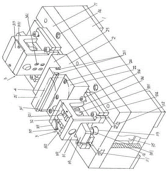
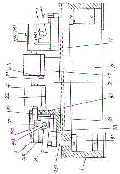
[0025] See figure 1 and figure 2, a base 1 with a rec...


PUM


Abstract

The invention provides a clamp used for machining a glass die and belongs to the technical field of tool clamps. The clamp comprises a base, a die joint face limiting base and a pair of die outer circular face clamping mechanisms, wherein the upper portion of the base is fixedly provided with a base platform, and the position, corresponding to the lower side of the base platform, of the base is provided with a base cavity; the die joint face limiting base is arranged on the upward side of the base platform and is located in the middle of the length direction of the base platform; the die outer circular face clamping mechanisms are arranged on the upward side of the base platform, one of the die outer circular face clamping mechanisms corresponds to the left side of the die joint face limiting base and the other die outer circular face clamping mechanism corresponds to the right side of the die joint face limiting base. The clamping requirement of a numerical control machining center machining a reference position on the end face of a semi-die blank of the die can be met; due to the fact that the overall structure is simple, the clamp is very convenient to manufacture and assemble, a good automatic clamping effect can be reflected, and the clamping operation difficulty of workers can be reduced.

Description

technical field [0001] The invention belongs to the technical field of tooling fixtures, and in particular relates to a fixture for processing glass mold dies. Background technique [0002] Glass mold is an important equipment for manufacturing glass containers such as various beer bottles, red wine bottles, beverage bottles and even cosmetic bottles for daily use. Steel is used as the material. Firstly, the steel round bar is cut according to the size requirements of the die, and then cut in the center, and then a series of processes such as positioning reference plane processing, die clamping surface and die cavity processing are processed until the die that can be put into use is obtained. Molded products. For the technical information about the die, please refer to the invention patent authorization announcement number CN102730943B (the die structure of the glass mold used for manufacturing glass containers) and CN102775047B (the bimetallic die for the glass mold and it...

Claims


Application Information

Patent Timeline
Patent Type & Authority Patents(China)
IPC IPC(8): B23Q3/08
CPCB23Q3/061B23Q3/062
Inventor 晏庆宝韩志强马军英
Owner CHANGSHU JIANHUA MOLD TECH
Why Eureka
Try Eureka