
Diversion tunnel sequential blocking method for realizing continuous stream of down stream of high arch dam in storage period

A technology for diversion tunnels and high arch dams, which is used in water conservancy projects, hydroelectric power generation, hydroelectric power stations, etc., can solve the problems of the impact of diversion tunnels, the unfavorable tunnel structure safety, the tight construction period of bypass tunnel excavation and support, and the difficulty in layout. and other problems, to achieve the effect of improving the dam structure and stress distribution, the dam structure being safe and beneficial, and the power generation benefit being obvious.

Active Publication Date: 2014-11-26
CHANGJIANG SURVEY PLANNING DESIGN & RES
View PDF4 Cites 3 Cited by
  • Summary
  • Abstract
  • Description
  • Claims
  • Application Information

AI Technical Summary

Problems solved by technology

However, these two measures usually have certain problems and shortcomings, and the layout is difficult and the investment is large. The specific reasons are as follows:
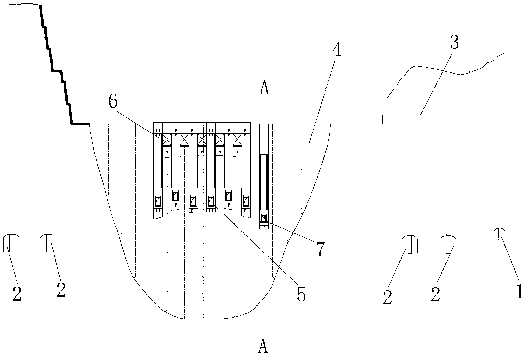
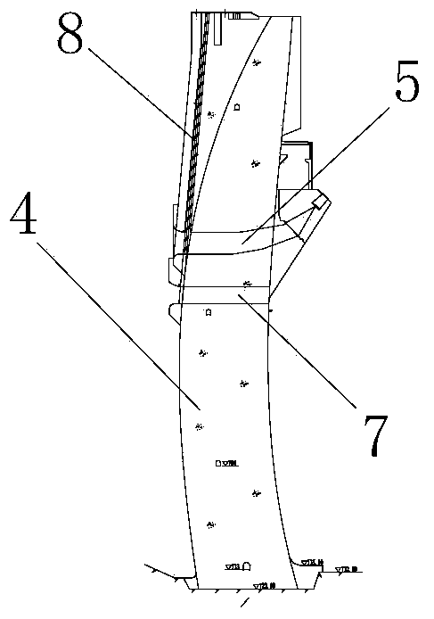
[0003] As for the scheme (1), setting diversion bottom holes 7 on the dam body 4 will bring many adverse effects: opening holes at the lower part of the dam body 4 of the high arch dam will have a great influence on the dam body structure and stress distribution , which is unfavorable to the safety of the dam body; the setting of the diversion bottom hole 7 and its supporting door slot increases the engineering quantity and project investment; affects the construction progress of the concrete pouring of the dam body, and will delay power generation for projects that take the dam construction time schedule as the key line The construction period reduces the power generation benefit; the permanent opening and closing equipment has not been formed when the diversion bottom hole 7 is lowered, and the temporary opening and closing equipment 8 of the gate needs to be added. figure 2 It can be seen that since the entrance side of the dam body 4 is an arc surface, and the temporary opening and closing device 8 of the gate is a plane, there is a huge gap between the arc surface and the plane, which requires a considerable amount of concrete consumption, which increases the project cost; The flow bottom hole is set at the lower elevation of the dam body, and part of the upstream cofferdam needs to be dismantled to meet the inflow conditions, and the engineering quantity and investment will be increased accordingly;
[0004] For the scheme (2), the bypass tunnel scheme is adopted, and there are the following unfavorable factors: after the diversion tunnel 1 and 2 are closed, the water flows back to the diversion tunnel 1 and 2 to discharge after the diversion tunnel 1 and 2 are released, and the construction period for the excavation and support of the bypass tunnel is tight ; When the ecological flow to be discharged is large, the conditions of the water flow into the diversion tunnel through the bypass tunnel are complicated, and the impact on the diversion tunnel, cavitation, etc. are unfavorable to the safety of the tunnel structure

Method used


Image

  • Diversion tunnel sequential blocking method for realizing continuous stream of down stream of high arch dam in storage period
  • Diversion tunnel sequential blocking method for realizing continuous stream of down stream of high arch dam in storage period
  • Diversion tunnel sequential blocking method for realizing continuous stream of down stream of high arch dam in storage period

Examples


Embodiment Construction

[0026] The present invention will be described in further detail below in conjunction with the accompanying drawings and embodiments, but these embodiments should not be construed as limiting the present invention.

[0027] see Figure 4 to Figure 5 , the present invention realizes the sequential sealing method of the diversion tunnel in the downstream of the high arch dam water storage period without interruption, involving the diversion tunnel 1 to be transformed, other diversion tunnels 2, the mountain body 3, the dam body 4, the middle hole 5 and the surface hole 6.

[0028] The arch dam body 4 is integrated with the mountain body 3. With the progress of the construction of the arch dam body 4, the middle hole 5 and the surface hole 6 will be constructed at the higher elevation of the arch dam body 4 in the future as permanent discharge channels. What is synchronized with the construction of the dam body 4 is that the diversion tunnel 1 to be reformed and other diversion ...


PUM


Abstract

The invention discloses a diversion tunnel sequential blocking method for realizing continuous stream of the down stream of a high arch dam in the storage period. The diversion tunnel sequential blocking method comprises the following steps that firstly, a diversion tunnel to be modified and a first lateral hole are selected in the dry season before gate blocking of the diversion tunnel, a lower half hole of the first lateral hole is blocked, the elevation of the bottom of the first lateral hole is heightened, the height of the opening of the first lateral hole is reduced, and the original size of the opening of a second lateral hole is reserved; secondly, the first lateral hole and the second lateral hole are respectively provided with a bulkhead gate, the second lateral hole which is not modified is blocked through the gate before water storage of a reservoir, and water is supplied to the down stream through the opening of an upper half hole of the first lateral hole; thirdly, after the water level of the reservoir meets the requirement that ecological flow can be discharged by a dam body permanent flood discharging hole, the gate of the opening of the upper half hole of the first lateral hole is closed, and the stream is not cut off in the gate closing process. The diversion tunnel sequential blocking method has the advantages of avoiding stream cutoff of the down stream in the gate closing process, simplifying the dam body structure, shortening the work period, increasing electricity generation gains and reducing engineering investment, and can be widely applied to the technical field of water conservancy and hydropower construction diversion.

Description

technical field [0001] The invention relates to the technical field of diversion in water conservancy and hydropower construction, in particular to a method for sequentially sealing diversion tunnels to realize continuous flow in the downstream of a high arch dam during storage. Background technique [0002] For hydropower projects where high arch dams are built in alpine and canyon areas, diversion methods such as cofferdams to block the river bed and diversion tunnels to discharge are usually used during construction. In the later stage of diversion construction, when the lower gate of the diversion tunnel is blocked, the water level of the reservoir gradually rises. Before the water level reaches the elevation of the permanent spillway hole of the high arch dam, the water flow has no discharge channel, which leads to the dehydration and interruption of the downstream river, which makes the aquatic life during the storage period The ecology is destroyed, which has adverse ...

Claims


Application Information

Patent Timeline
IPC IPC(8): E02B9/04
CPCY02A20/402Y02E10/20
Inventor 翁永红李勤军石运深范五一徐唐锦胡清义马永锋彭作为牛运华钱军祥漆祖芳李蘅李伟段寅饶志文
Owner CHANGJIANG SURVEY PLANNING DESIGN & RES
Learn More