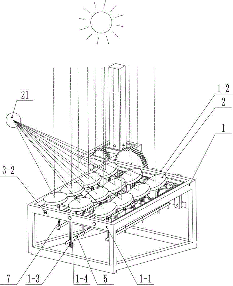
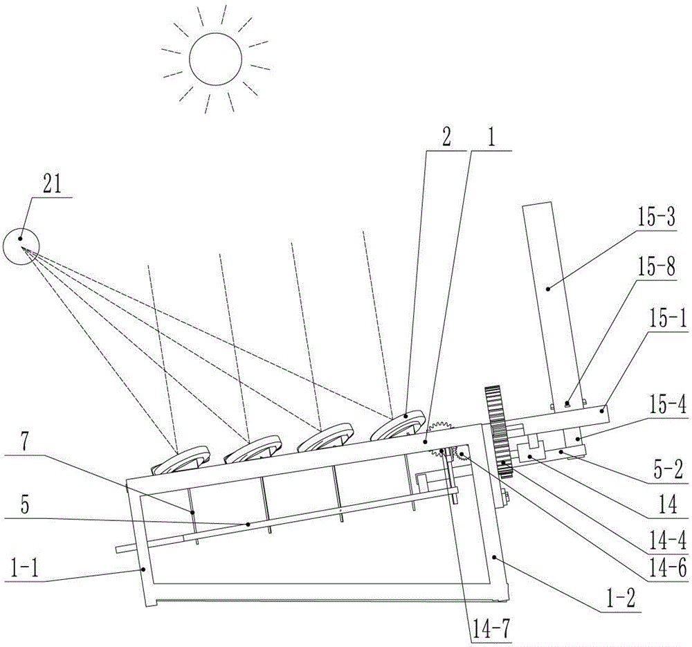
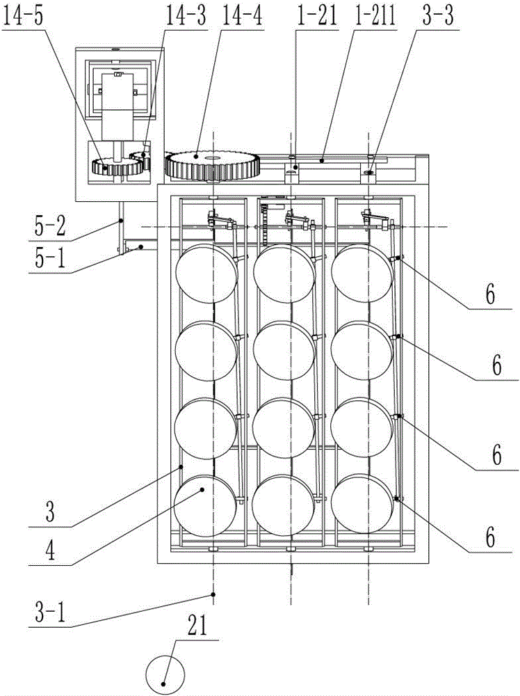
[0005] The beneficial effects of the solar concentrating device provided by the present invention are: since the solar concentrating device provided by the present invention is planar, not in the shape of a pot body, when multiple reflecting mechanisms move to track the sun, only the multiple reflecting mechanisms are moving. The concentrating point of each reflector is always fixed, and the object to be heated can be fixed and installed without moving together with multiple reflectors. Therefore, the overall
drag coefficient of the solar concentrating device is greatly reduced, and the windproof ability is enhanced. Large-scale solar concentrating devices It can be completed through
assembly, the manufacturing difficulty and manufacturing cost are greatly reduced, the installation is more convenient, and the use is not limited. Another major effect of the present invention is that the mechanism for realizing the rotation of multiple mirrors is simple in structure and low in manufacturing cost. The reflection mechanism includes left and right The
turret, multiple reflector mechanisms and front and rear movement linkages, because the left and right turrets are rotatable around the central axis, the multiple reflector mechanisms are sequentially arranged and installed on the left and right turrets along the front and rear length directions of the left and right turrets, that is, Said that a plurality of reflector mechanisms are arranged in a straight line, the left and right turrets can rotate left and right, and the multiple reflector mechanisms installed on the left and right turrets can also rotate left and right with the left and right turrets, and each reflector mechanism includes a horizontal Rods, couplings, vertical rods and reflectors, the crossbar has a crossbar axis, the coupling has a coupling axis, the reflector is installed on the crossbar, and the crossbar is installed on the left and right turrets. The upper end of the
vertical bar is hinged with the
horizontal bar through a coupling, and the lower end of the
vertical bar is hinged on the front and rear movement link. The left and right turrets, horizontal bars and reflectors can rotate around the central axis. The mirror can rotate around the axis of the cross bar. When the
vertical bar, the cross bar, the joint shaft and the reflector rotate around the axis of the cross bar, the front and rear movement link moves back and forth along the central axis in the front and rear length direction of the left and right turrets. That is to say, the reflector can rotate back and forth, and when the reflector rotates back and forth, the vertical bar, coupling shaft and cross bar rotate back and forth together, and the forward and backward movement link moves back and forth. Rotate together, when the mirror rotates left and right, the vertical rod does not move. The technical problem solved by the front and rear movement link is that when one mirror rotates back and forth, the other mirrors also rotate back and forth together, so that multiple mirrors can be rotated in phase. Linkage, the bottom of the reflector is hinged to the cross bar at the
hinge point, and the bottom of the reflector has a pushing mechanism that pushes the mirror to rotate around the
hinge point relative to the cross bar. When the left and right turrets, the cross bar and the reflector rotate around the central axis , the pushing mechanism pushes the reflector to rotate around the
hinge point relative to the crossbar, and the magnitude of the push mechanism pushing the reflector to rotate around the hinge point relative to the crossbar increases sequentially from close to the front side of the frame to away from the front side of the frame, that is to say When the reflector rotates left and right, there is a push mechanism to push the reflector to rotate left and right relative to the cross bar around the hinge point. The reflector has
double rotation, and the closer the reflector is to the front of the frame, the push mechanism pushes the reflector around the hinge point relative to the cross bar. The smaller the range of left and right rotation is, the farther the reflector is from the front side of the frame. Arranged in a straight line, so the farther away the reflector from the object to be heated needs to be, the larger the range of left and right rotation is, so that the multiple focal points of multiple reflectors can be gathered together when they rotate left and right, and will not be scattered. Simply put, it is To prevent multiple light-concentrating points from being scattered when multiple reflectors rotate left and right, the
acute angle formed between the axis of the cross bar and the central axis on the horizontal plane decreases in turn from close to the front side of the rack to far away from the front side of the rack , that is to say, the farther away from the front side of the frame the greater the inclination of the axis of the crossbar relative to the central axis is, the greater the inclination of the mirror will be. The inclination between the axis of the crossbar and the central axis solves the technology The problem is to prevent multiple light-concentrating points from being scattered when multiple reflectors rotate back and forth. The inclinations between the central axes are all vertical, but since there can be multiple rows of left and right turrets on the frame, the focal point can be on the central axis of one of the left and right turrets, or not on any of the left and right turrets. On the central axis of the frame, in order to make more effective use of the collection space, the frame is made into a square structure instead of a
single row of a left and right
turret structure, so the structural setting of the inclination between the axis of the cross bar and the central axis can make the The reflectors on the multiple rows of left and right turrets are all focused on the focus point, and the focus point may not be restricted to be on the central axis of the left and right turrets. The
acute angle formed on the horizontal plane decreases successively from close to the front side of the frame to far away from the front side of the frame. The inclination will also be larger, and the technical problem to be solved by the inclination between the axis of the cross bar and the axis of the coupling shaft is to avoid the dispersion of a plurality of focusing points when the plurality of reflectors rotate left and right, and the forward and backward movement The length of the vertical bar between the link and the cross bar decreases successively from near the front of the frame to far away from the front of the frame, that is to say, the closer the distance between the front and rear movement of the front and rear of the frame is between the link and the cross bar. The longer the length of the vertical rod, the shorter the length of the vertical rod between the forward and backward movement link and the cross bar, the farther away from the front side of the frame, and the larger the range of front and rear rotation of the reflector near the front side of the frame. The farther away from the front side of the frame the mirror needs to be, the smaller the range of forward and backward rotation is, wherein the length of the vertical bar between the front and rear movement link and the cross bar is reduced sequentially from close to the front side of the frame to far away from the front side of the frame. The technical problem to be solved is to prevent multiple light-concentrating points from being scattered when multiple reflectors rotate back and forth. Therefore, by setting up this mechanism, only two driving mechanisms need to be installed to drive multiple reflectors to rotate left and right and forward and backward. Realize that the focusing points of multiple reflectors are always fixed, and the focusing points between multiple reflectors will not be scattered, and there is no need to drive each reflector, so that the structure is simpler and the manufacturing cost is greatly reduced


