
Optical communication apparatus

A technology of optical communication and light guide part, which is applied in the field of optical communication, can solve the problems of deformation of non-heat-resistant components of optical waveguide components, affecting the transmission efficiency of optical communication devices, and the difficulty of effective heat dissipation of optical communication devices, so as to achieve the effect of ensuring transmission efficiency

Inactive Publication Date: 2014-11-26
SCIENBIZIP CONSULTINGSHENZHENCO
View PDF5 Cites 7 Cited by
  • Summary
  • Abstract
  • Description
  • Claims
  • Application Information

AI Technical Summary

Problems solved by technology

Therefore, it is difficult for the optical communication device to effectively dissipate heat. If the heat accumulates to a certain extent, it will cause deformation of non-heat-resistant components such as the optical waveguide element, thereby affecting the transmission efficiency of the optical communication device.

Method used


Image

  • Optical communication apparatus

Examples


Embodiment Construction

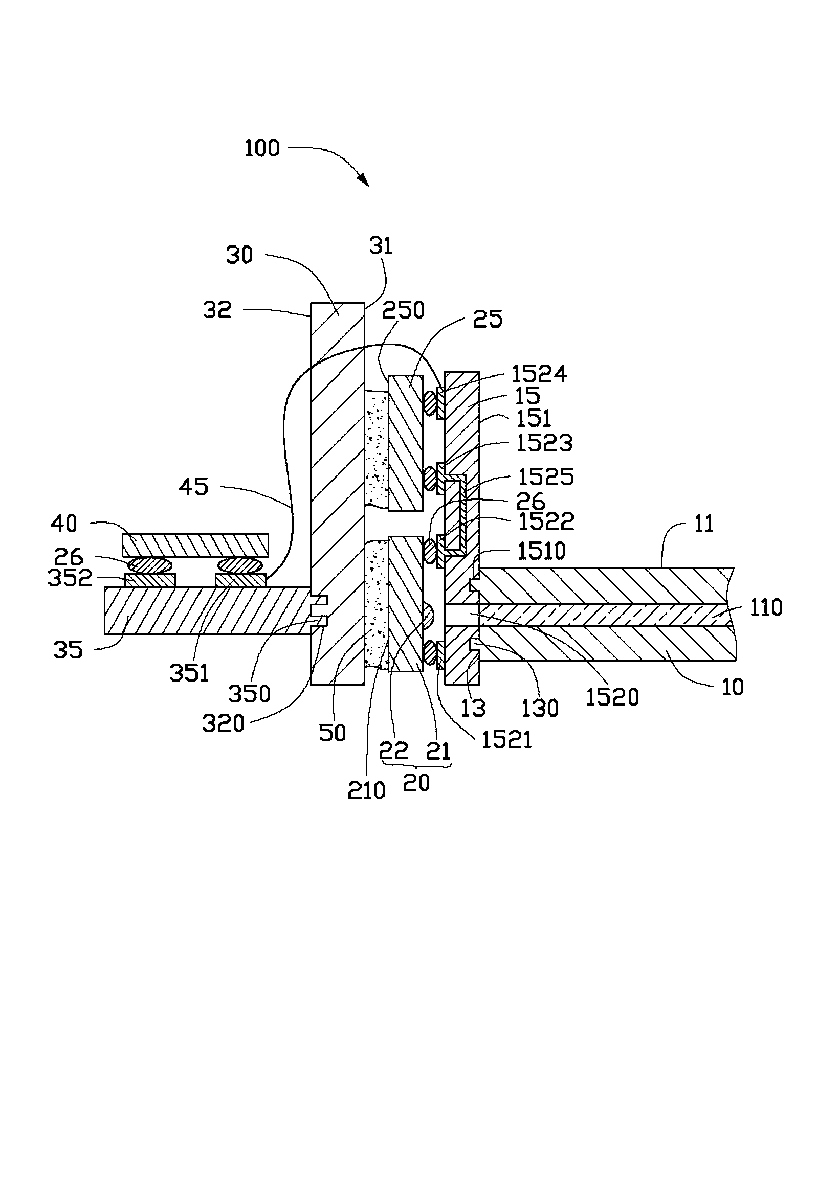
[0010] Such as figure 1 As shown, an optical communication device 100 provided for an embodiment of the present invention includes a planar optical waveguide 10, a first substrate 15, a photoelectric element 20, a first controller 25, a first heat sink 30, a The second substrate 35 and a processor 40 .

[0011] The planar light guide 10 includes an upper surface 11 and a first side 13 . The first side 13 is substantially perpendicular to the upper surface 11 . A light guiding portion 110 is formed inside the planar light waveguide 10 . Two first positioning posts 130 extend along the direction perpendicular to the first side 13 of the first side 13 of the planar optical waveguide 10 . The two first positioning posts 130 are distributed on both sides of the light guide part 110 and are symmetrical with respect to the light guide part 110 .

[0012] In this embodiment, in order to enhance the heat dissipation efficiency of the first substrate 15 , the first substrate 15 is a...


PUM


Abstract

The invention relates to an optical communication apparatus comprising a planar optical waveguide, a first substrate, a photoelectric element, a first controller, a first radiating plate, a second base plate and a processor. The planar optical waveguide includes an upper surface and a first side surface; the first substrate fixed at the first side surface includes a first side wall connected with the first side surface and a second side wall deviated from the first side wall; the photoelectric element and the first controller are fixed at the second side wall and are electrically connected; the photoelectric element includes a first adhesive surface far away from the first substrate; the first controller includes a second adhesive surface far away from the first substrate; the first radiating plate is fixed at the first adhesive surface and the second adhesive surface by a radiating adhesive; one side surface of the second substrate is fixed at the first radiating plate; and the processor is carried at the second substrate and is electrically connected with the first controller.

Description

technical field [0001] The present invention relates to the field of optical communication, in particular to an optical communication device. Background technique [0002] In optical communication devices, information is transmitted in the form of optical signals, and calculated and processed in the form of electrical signals. Existing optical communication devices generally include a light emitting element, a light receiving element, an optical waveguide, a driver chip, an operation chip, a control chip, and a storage element. The light-emitting element, light-receiving element, optical waveguide, driving chip, computing chip, control chip, storage element and other components are arranged in a narrow space on the circuit board. The light-emitting element, light-receiving element, driver chip, computing chip, control chip and storage element will generate a lot of heat during the working process, which is limited by the volume of the optical communication device. The light...

Claims


Application Information

Patent Timeline
Patent Type & Authority Applications(China)
IPC IPC(8): G02B6/42
Inventor 曾国峰
Owner SCIENBIZIP CONSULTINGSHENZHENCO
Learn More