Dynamic scheduling methods and devices in base station and UE

A dynamic scheduling and one-to-one correspondence technology, which is applied in space transmit diversity, radio transmission systems, electrical components, etc., can solve problems such as high complexity and complex implementation, so as to improve robustness, realize space diversity, and improve transmission performance Effect

Active Publication Date: 2018-06-05
SHANGHAI LANGBO COMM TECH CO LTD
View PDF3 Cites 13 Cited by
  • Summary
  • Abstract
  • Description
  • Claims
  • Application Information

AI Technical Summary

Problems solved by technology

Another implementation method is that the UE blindly detects the control signaling within the time window corresponding to all beamforming vectors, which will bring more complexity and more complicated implementation

Method used


Image

  • Dynamic scheduling methods and devices in base station and UE
  • Dynamic scheduling methods and devices in base station and UE
  • Dynamic scheduling methods and devices in base station and UE

Examples


Embodiment 1

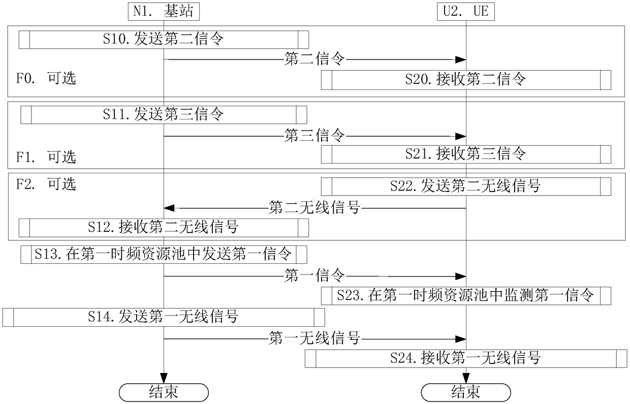
[0198] Embodiment 1 illustrates a flowchart of a first signaling transmission according to the present invention, as shown in the attached figure 1 shown. attached figure 1 In , the base station N1 is the maintenance base station of the serving cell of the UE U2. The steps identified in boxes F0 to F2 are optional.

[0199] for base station N1 , the second signaling is sent in step S10, the third signaling is sent in step S11, the second wireless signal is received in step S12, the first signaling is sent in the first time-frequency resource pool in step S13, and the In step S14, the first wireless signal is sent.

[0200] for UE U2 , receiving the second signaling in step S20, receiving the third signaling in step S21, sending the second wireless signal in step S22, monitoring the first signaling in the first time-frequency resource pool in step S23, and In step S24, the first wireless signal is received.

[0201] As a sub-embodiment, the first signaling is a downlin...

Embodiment 2

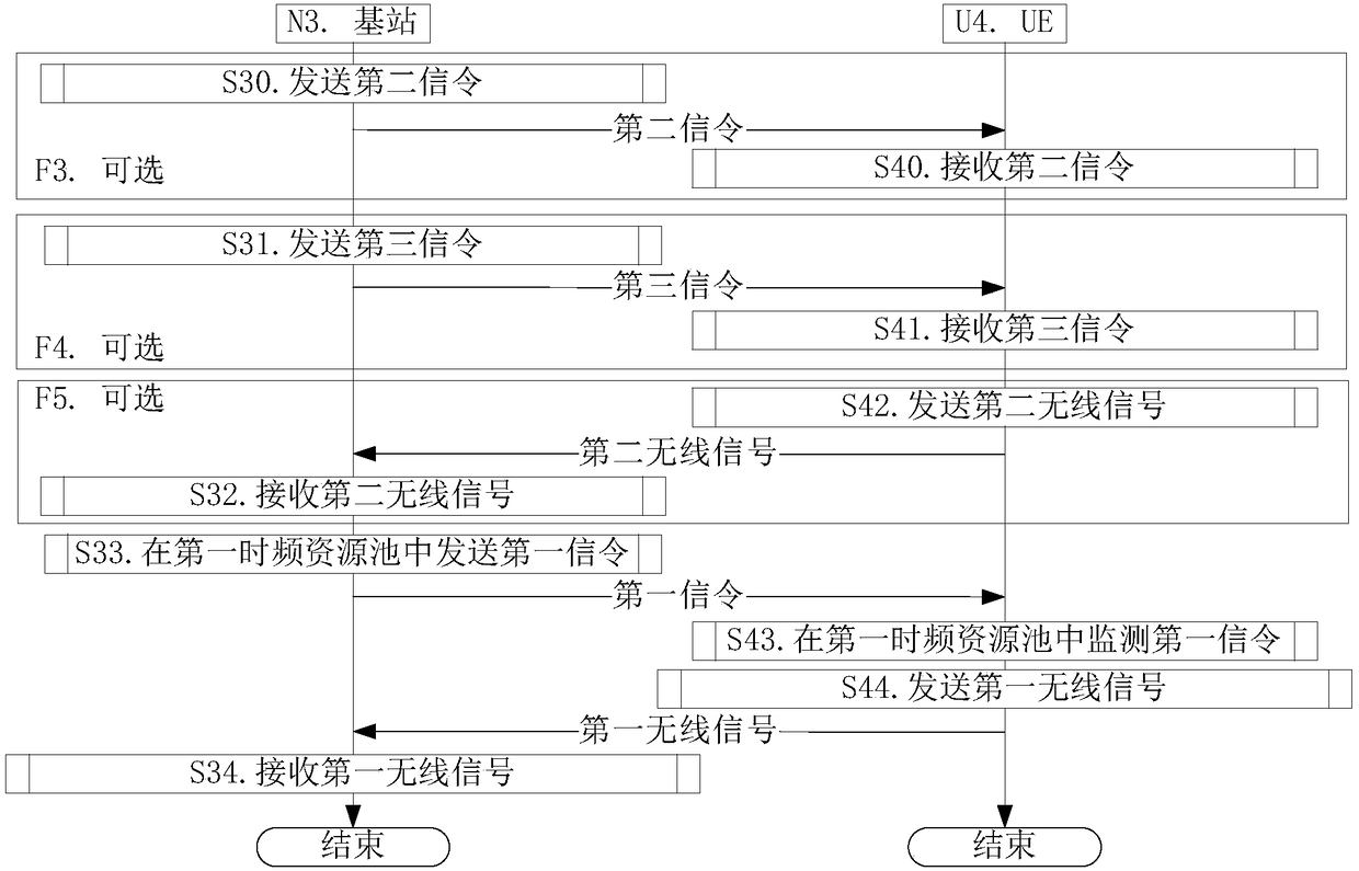
[0204] Embodiment 2 illustrates another flow chart of the first signaling transmission according to the present invention, as shown in the attached figure 2 shown. attached figure 2 In , the base station N3 is the maintenance base station of the serving cell of the UE U4. The steps identified in boxes F3 to F5 are optional.

[0205] for base station N3 , send the second signaling in step S30, send the third signaling in step S31, receive the second wireless signal in step S32, send the first signaling in the first time-frequency resource pool in step S33, and In step S34, the first wireless signal is received.

[0206] for UE U4 , receiving the second signaling in step S40, receiving the third signaling in step S41, sending the second wireless signal in step S42, monitoring the first signaling in the first time-frequency resource pool in step S43, and In step S44, the first wireless signal is sent.

[0207] As a sub-embodiment, the first signaling is an uplink grant...

Embodiment 3

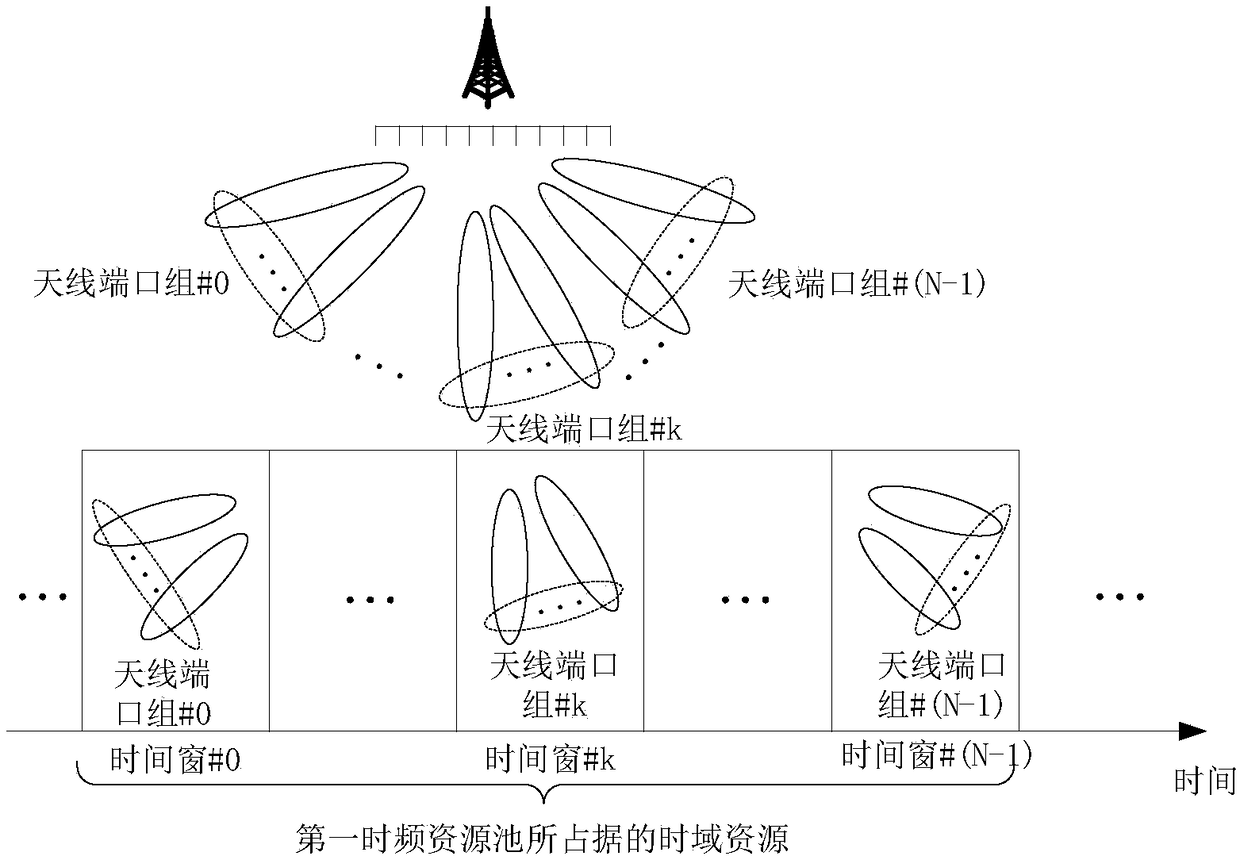
[0210] Embodiment 3 illustrates a schematic diagram of N time windows. as attached image 3 As shown, the N time windows are in one-to-one correspondence with the N antenna port groups. Time window #0 corresponds to antenna port group #0, time window #k corresponds to antenna port group #k, and time window #(N-1) corresponds to antenna port group #(N-1). Wherein, k is a positive integer greater than 0 and less than (N-1).

[0211] As a sub-embodiment, the number of antenna ports included in different antenna port groups is the same.

[0212] As a sub-embodiment, at least two different antenna port groups include different numbers of antenna ports.

[0213] As a sub-embodiment, the antenna port is formed by stacking multiple antennas through antenna virtualization, and mapping coefficients from the multiple antennas to the antenna port form a beamforming vector.

[0214] As a sub-embodiment, the number of multi-carrier symbols occupied by any one of the N time windows is th...


PUM


Abstract

The invention discloses dynamic scheduling methods and devices in a base station and UE. The UE monitors a first signal in a first time-frequency resource pool; the first time-frequency resource pooloccupies N time windows in the time domain; the N time windows and N antenna port groups are in one-to-one correspondence; the first signal is a physical layer signal; detection for X times at most iscarried out for the first signal; the detection for X times is separately for X RE sets; in the X RE sets, Y1 first-type RE sets exist; REs included in the first-type RE sets are positioned in N1 time windows; and the N1 time windows belong to the N time windows. According to the dynamic scheduling methods and devices in the base station and the UE disclosed by the invention, the Y1 first-type REsets are designed; furthermore, the first signal is transmitted on different antenna port groups; therefore, the first signal transmission robustness is improved; and thus, the control signal transmission performance and the overall spectral efficiency of a system are improved.

Description

technical field [0001] The present invention relates to a transmission method and device in a wireless communication system, in particular to a transmission scheme and device used for dynamic scheduling. Background technique [0002] Massive MIMO (Multiple Input Multiple Output, Multiple Input Multiple Output) has become a research hotspot in the next generation of mobile communications. In large-scale MIMO, multiple antennas use beamforming to form narrower beams pointing in a specific direction to improve communication quality. Both data channels and control channels can be multi-antenna beamforming to improve transmission quality. [0003] In traditional LTE (Long Term Evolution, long-term evolution) and LTE-A (Long Term Evolution Advanced, enhanced long-term evolution) systems, the physical layer control channel corresponding to DCI (Downlink Control Information) is sent in a non-beamforming manner of. According to the discussion of 3GPP (3rd Generation Partner Projec...

Claims


Application Information

Patent Timeline
Patent Type & Authority Applications(China)
IPC IPC(8): H04B7/0408H04B7/0413H04B7/06
CPCH04B7/0408H04B7/0413H04B7/0617
Inventor 蒋琦
Owner SHANGHAI LANGBO COMM TECH CO LTD
Why Eureka
Try Eureka