Data transmission method, data transmission device and data transmission system

A data transmission method and technology of a data transmission device, applied in the field of communication, can solve the problem that a terminal cannot correctly complete data interaction and the like

Active Publication Date: 2013-05-15
ZTE CORP
View PDF5 Cites 15 Cited by
  • Summary
  • Abstract
  • Description
  • Claims
  • Application Information

AI Technical Summary

Problems solved by technology

[0008] Aiming at the problem in the related art that when the above-mentioned new transmission scheme is used for data transmission, the terminal cannot correctly complete the data interaction, the present invention provides a data transmission method, device and system to at least solve the above-mentioned problem

Method used


Image

  • Data transmission method, data transmission device and data transmission system
  • Data transmission method, data transmission device and data transmission system
  • Data transmission method, data transmission device and data transmission system

Examples


Embodiment 1

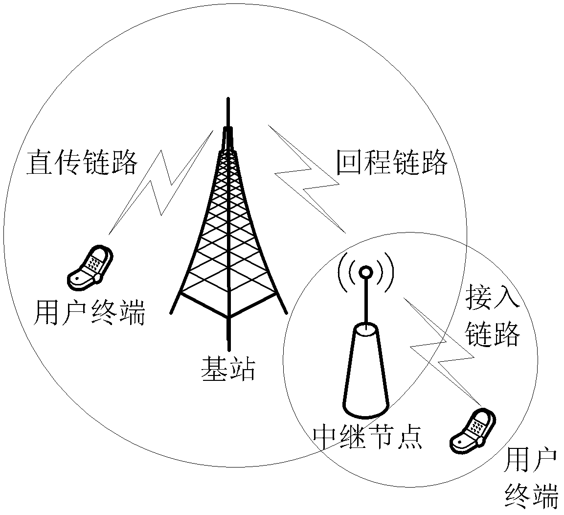
[0067] The network side device in this embodiment is described by taking RN as an example, as Figure 4 In the schematic diagram of the network structure shown, the RN covers two UEs (hereinafter referred to as UE1 and UE2 for short) that need to perform data interaction, and the data interaction can be directly completed by the RN without going through a relay link, and it is assumed that this embodiment The data interaction adopts the SDD transmission scheme. For example, in the first stage, UE1 and UE2 occupy different subcarriers to send data data1 and data2 to RN respectively, and in the second stage, RN will XOR the received data1 and data2 (ie data3=data1 data2), send data data3 to UE1 and UE2, that is to say, the grant information and / or data information obtained by UE1 and UE2 in the second stage are the same, that is, corresponding to the grant information and / or data information of data3. Figure 5 Shown is a flow chart of two UEs interacting data under RN coverage...

Embodiment 2

[0077] The network side device in this embodiment is described by taking eNB as an example, as Image 6 In the schematic diagram of the network structure shown, the eNB covers three UEs (hereinafter referred to as UE1, UE2 and UE3 for short) that need to perform data interaction, and it is assumed that the data interaction between UE1 and eNB in ​​this embodiment adopts a conventional transmission scheme (that is, a non-specific transmission scheme, such as a unicast transmission scheme), the data interaction between UE1 and UE2 adopts the SDD transmission scheme, and the data interaction between UE1 and UE3 also adopts the SDD transmission scheme.

[0078] Such as Figure 7 Shown is a flow chart of three UEs interacting data under eNB coverage, and the method includes the following steps (step S702-step S730):

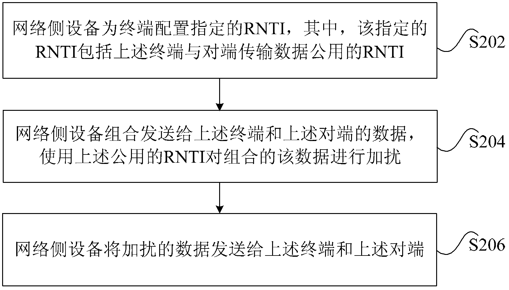
[0079] In step S702, the eNB configures designated RNTIs for UE1, UE2 and UE3 respectively, and the designated RNTIs are C-RNTI-1, C-RNTI-2 and C-RNTI-3 respectively...

Embodiment 3

[0110] The network-side device in this embodiment takes eNB as an example for illustration. When two UEs (hereinafter referred to as UE1 and UE2 for short) under the coverage of eNB need to exchange data, it is assumed that UE1 and UE2 adopt D2D (Device to Device) transmission. plan. That is, UE1 directly sends data to UE2, without the need for transfer by other nodes. Such as Figure 9 Shown is a flowchart of two UEs under eNB coverage exchanging data, the method includes the following steps (step S902-step S912):

[0111] In step S902, the eNB configures C-RNTI-1 and C-RNTI-2 for UE1 and UE2 respectively.

[0112] The C-RNTI-1 is used to obtain the grant information of data1 (hereinafter referred to as grant-1), and the C-RNTI-2 is used to obtain the grant information of data2 (hereinafter referred to as grant-2).

[0113] Step S904, determine whether UE1 adopts the D2D transmission scheme, if UE1 needs to establish a D2D transmission scheme with UE2, execute step S906, i...


PUM


Abstract

The invention discloses a data transmission method, a data transmission device and a data transmission system. The method includes that a network side device configures a pointed radio network temporary identity (RNTI) for a terminal, wherein the pointed RNTI comprises a public RNTI for data transmission between the terminal and an opposite terminal; the network side device combines data which are sent to the terminal and the opposite terminal, and the combined data are disturbed by the public RNTI; and the disturbed data are sent to the terminal and the opposite terminal through the network side device. Through the data transmission method, the problem that when a new transmission scheme is adopted to carry out data transmission in a correlation technique, the terminal cannot accurately finish data interaction is solved, efficiency of the data transmission is ensured, and reliability of the data transmission is improved.

Description

technical field [0001] The present invention relates to the communication field, in particular, to a data transmission method, device and system. Background technique [0002] The complete two-way data interactive communication process between two user equipments (User Equipment, UE for short) in the advanced long-term evolution system (Long Term Evolution Advanced, referred to as LTE-A) generally includes 4 stages, that is, the first stage is UE1 sends data data1 to evolved Node B (evolved Node B, referred to as eNode-B or eNB). In the second stage, eNode-B sends data data1 to UE2. In the third stage, UE2 sends data data2 to eNode-B. In phase 4, eNode-B sends data data2 to UE1. After these four stages, UE1 and UE2 complete a two-way data exchange communication process. More specifically, the eNode-B needs to send grant grant information to the terminal (such as UE), including downlink grant information (Downlink grant, DL grant for short) and uplink grant information (Upl...

Claims


Application Information

Patent Timeline
Patent Type & Authority Applications(China)
IPC IPC(8): H04L1/06
Inventor 毕峰吴栓栓梁枫袁明杨瑾
Owner ZTE CORP
Why Eureka
Try Eureka