Multi light source large view field spliced illumination system

An illumination system and a large field of view technology, applied in the field of integrated circuit equipment manufacturing, can solve the problems of decreased uniformity of the illumination field of view, unfavorable work of lithography equipment, etc., and achieve the effect of overcoming image surface unevenness and overcoming manufacturing difficulties.

Active Publication Date: 2014-11-26
SHANGHAI MICRO ELECTRONICS EQUIP (GRP) CO LTD
View PDF7 Cites 7 Cited by
  • Summary
  • Abstract
  • Description
  • Claims
  • Application Information

AI Technical Summary

Problems solved by technology

This solution mainly solves two problems: First, couple and decompose the energy of the light source into the branched exposure subsystem
When a single lamp goes out or fails, the initial light energy distribution on the object surface will change g

Method used


Image

  • Multi light source large view field spliced illumination system
  • Multi light source large view field spliced illumination system
  • Multi light source large view field spliced illumination system

Examples


Example Embodiment

[0033] The specific embodiments of the present invention will be described in detail below with reference to the drawings.

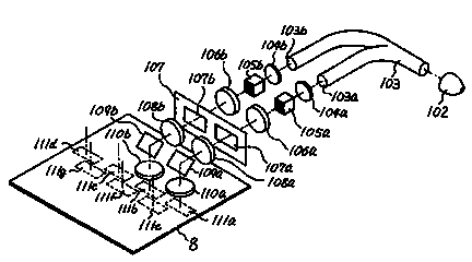
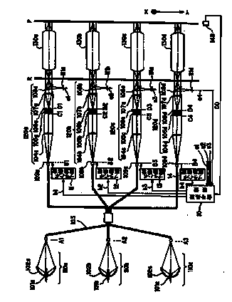
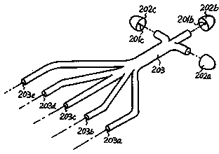
[0034] Such as Figure 5 As shown, the multi-light source large-field splicing illumination system of the present invention includes a plurality of light sources 1, and each light source 1 corresponds to a plurality of optical fibers 2, and the light enters a plurality of coupling lens groups 3 through the plurality of optical fibers 2 respectively. The angle of light coupled by the coupling lens group 3 is adjusted by the flat plate adjusting device 4, and the light is homogenized by the light homogenizing device 5, and then the required illumination with a certain numerical aperture, size and uniformity is formed on the mask plate 7 through the relay lens group 6 Field of view. After the projection objective 8 is passed, a slit diaphragm is provided in the projection objective 8 to form a trapezoidal exposure field of view 9 on the image plane of the proj...


PUM


Abstract

The invention provides a multi light source large view field spliced illumination system. The system is characterized by comprising a plurality of light sources, a plurality of optical fibers, and a plurality of illumination subsystems; wherein at least an optical fiber is arranged between each light source and each illumination subsystem, the lights are emitted by the light sources and introduced into the plurality of illumination subsystems through the optical fibers, and the illumination subsystems process the lights and form an illumination view field on a mask plate. The system adopts a technical scheme of coupling multiple optical fibers to overcome the problems that a large-diameter multi-branch fiber is hard to manufacture and the large-diameter multi-branch fiber limits the design and installation of lamp house. Moreover, a parallel plane/wedge plane adjusting device is provided to overcome the image plane inhomogeneity caused by the fault of a single mercury lamp.

Description

technical field [0001] The invention relates to the field of integrated circuit equipment manufacturing, in particular to a multi-light source and large-field-of-view splicing lighting system for photolithography equipment. Background technique [0002] With the development of thin film field effect transistor TFT lithography technology, the size of the substrate is getting larger and more integrated units, it is difficult for a single lighting system to meet the needs of TFT lithography. In integrated circuit IC, packaging and other stepping lithography equipment, the maximum illumination field of view is generally 8 inches, and scanning lithography only has a larger field of view in the scanning direction, generally not exceeding 10 inches. However, the exposure field of view of TFT of more than five generations is above 17 inches, so the illumination field of view of a single lens is far from meeting the requirements of large field of view lithography. [0003] Using mul...

Claims


Application Information

Patent Timeline
IPC IPC(8): G03F7/20F21V8/00
Inventor 景磊张祥翔陈璐玲
Owner SHANGHAI MICRO ELECTRONICS EQUIP (GRP) CO LTD
Why Eureka
Try Eureka