Method and special-purpose device for household electrical interconnection intercommunication bottom transmission
A technology of interconnection and home appliances, which is applied in the underlying transmission field of home appliance interconnection and intercommunication, can solve the problems of failure to accommodate home appliance interconnection and intercommunication, and achieve the effects of moderate indoor transmission distance, enhanced anti-interference ability, and convenient installation
- Summary
- Abstract
- Description
- Claims
- Application Information
AI Technical Summary
Problems solved by technology
Method used
Image
Examples
specific Embodiment 1
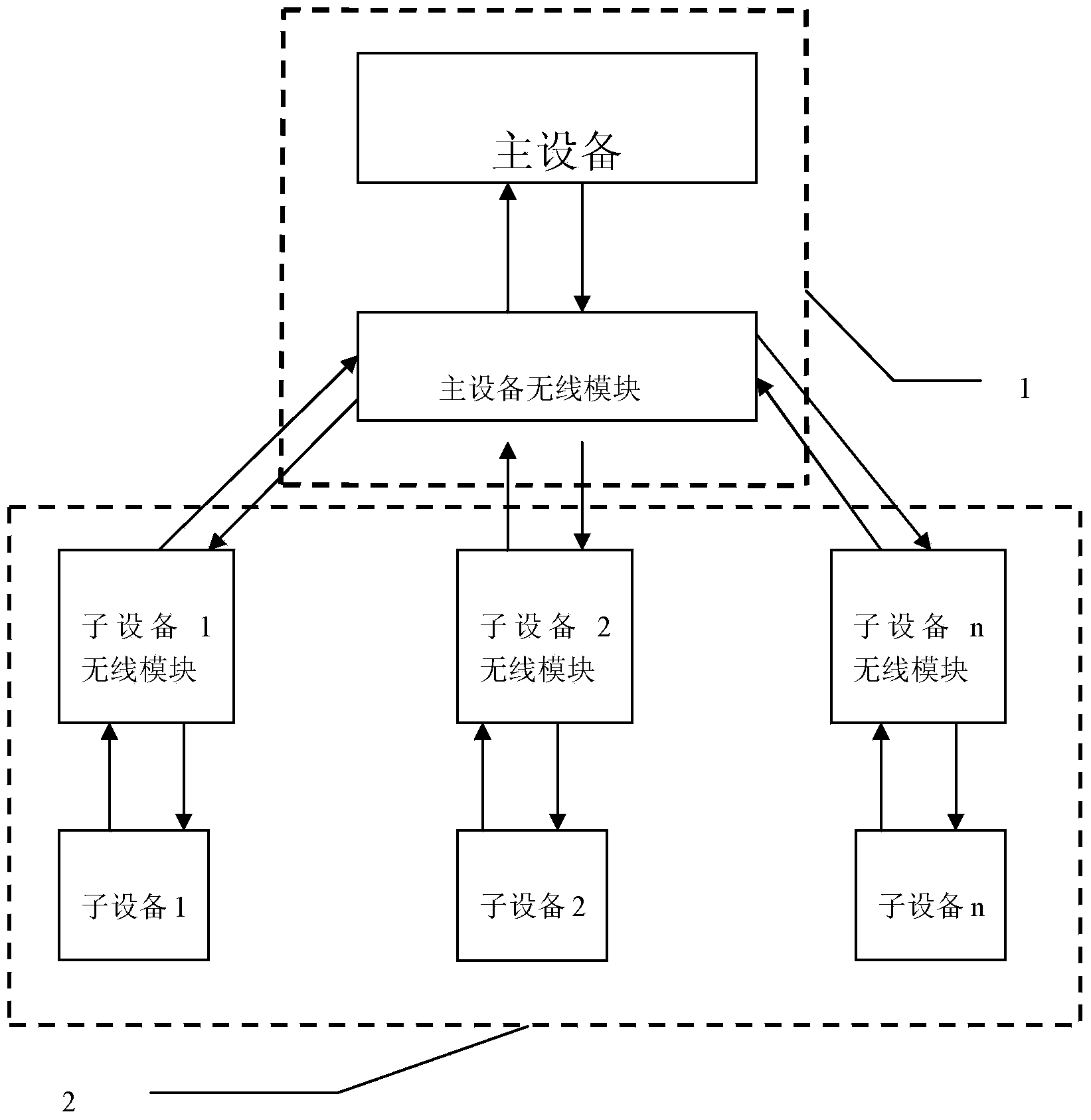
[0037] refer to figure 1 , the special device for interconnection and intercommunication underlying transmission of home appliances involved in this embodiment includes a main device node unit 1 and a sub-device node unit 2, the main device node unit 1 includes a main device and a main device wireless module, and the sub-device node unit 2 includes several sub-device node, each sub-equipment node is composed of a sub-equipment and a sub-equipment wireless module; the main equipment node unit 1 is connected to the sub-node unit 2 through a wireless network for data exchange; the main equipment has an SPI interface, and it passes through the SPI interface Connect the wireless module of the main device, and several I / O ports of the wireless module of the main device are bidirectionally connected to a sub-device through a wireless module of the sub-device, that is, the main device communicates with the sub-device through the wireless module of the main device, the wireless module o...
specific Embodiment 2
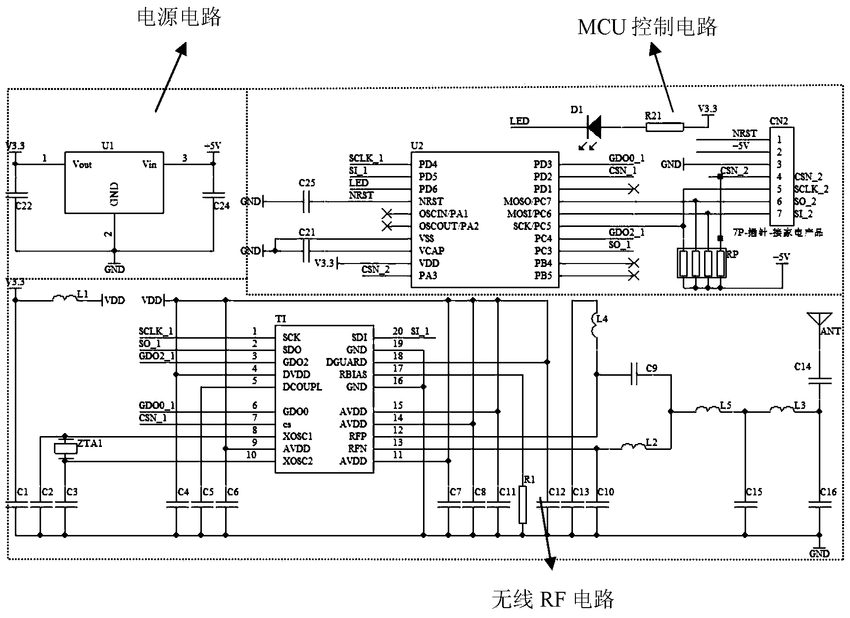
[0062] refer to image 3 , The feature of this embodiment is: the wireless module is composed of a power supply circuit, an MCU control circuit and a wireless chip circuit. The power supply circuit is composed of a voltage conversion IC U1, capacitors C22 and C24. The input terminal of U1 is connected to the 5V power input and one terminal of the capacitor C24, the output terminal of U1 is connected to one terminal of the capacitor C22, the ground terminal of U1 and the other terminals of the capacitors C22 and C24 are respectively grounded. The power supply circuit converts the external 5V DC power supply to 3.3V DC power supply for MCU and wireless chip. The MCU control circuit is composed of MCU controller U2, light-emitting diode LED1, capacitors C21, C25, resistor R21, resistance row RP1, and pin CN2. Among them, pins 1, 2, 13, 14, 19, and 20 of U2 are respectively connected to pins 1, 20, 2, 3, 7, and 6 of U3, and pins 4, 10, 15, 16, and 17 of U2 are respectively conne...
PUM
 Abstract
Description
Claims
Application Information
 - R&D
- Intellectual Property
- Life Sciences
- Materials
- Tech Scout
- Unparalleled Data Quality
- Higher Quality Content
- 60% Fewer Hallucinations
Browse by: Latest US Patents, China's latest patents, Technical Efficacy Thesaurus, Application Domain, Technology Topic, Popular Technical Reports.
© 2025 PatSnap. All rights reserved.Legal|Privacy policy|Modern Slavery Act Transparency Statement|Sitemap|About US| Contact US: help@patsnap.com


