Passive containment condensate injection system

A passive containment and injection system technology, applied in the field of passive containment condensate water injection system, can solve the problems of pressure vessel failure uncertainty, reactor safety risk, etc., and achieve lower temperature, simple structure, and prevent melt-through Effect

Active Publication Date: 2017-03-29
STATE NUCLEAR HUAQING BEIJING NUCLEAR POWER TECH R & D CENT +1
View PDF1 Cites 3 Cited by
  • Summary
  • Abstract
  • Description
  • Claims
  • Application Information

AI Technical Summary

Problems solved by technology

However, with the continuous increase of reactor power (such as CAP1700 or even higher), the formation and stratification mechanism of the core melt pool is not fully understood at present, and the cooling of the core melt only relies on the strategy of IVR-ERVC, and the pressure vessel The failure has great uncertainty, so the safety of the reactor will also have certain risks

Method used


Image

  • Passive containment condensate injection system
  • Passive containment condensate injection system

Examples


Embodiment 1

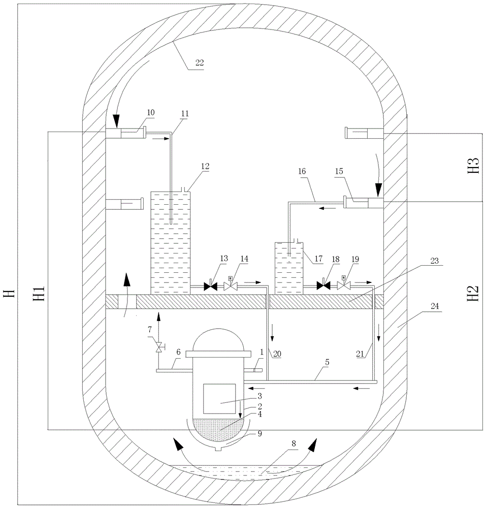
[0051] figure 1 It is a structural schematic diagram of a passive containment condensate water injection system arranged in the containment vessel 24 according to the first embodiment of the present invention (there are emergency water injection tanks 12, 17).

[0052] Such as figure 1 As shown, a nuclear reactor with a breach 1 , a reactor pressure vessel 2 , a core 3 , a pit 8 , and an internal melt retention-pressure vessel external cooling system (IVR-ERVC) 9 is contained in a containment vessel 24 . The operation platform 23 divides the inside of the containment vessel 24 into two inner spaces, upper and lower. The passive containment condensate injection system includes two sets of condensate collection structures, which are arranged between the top of the straight wall of the containment vessel 24 and the operation platform 23 . Among them, the high-level condensate collection structure (first height) is composed of a water collection groove 10 and a collection condui...

Embodiment 2

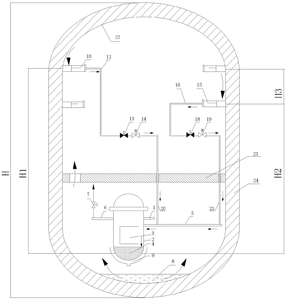
[0058] figure 2 It is a structural schematic diagram of a passive containment condensate water injection system arranged in the containment vessel 24 according to the second embodiment of the present invention (without an emergency water injection tank).

[0059] The present invention also provides another passive containment condensate water injection system, such as figure 2 shown. The main difference between this water injection system and Embodiment 1 is that the system is slightly modified, the structure is simplified, and the optional emergency water injection tanks 17 and 12 are removed. At the same time, the collection heights of the condensed water at two places were changed. The first height H1 and the second height H2 are respectively located at 75% of the total height H of the containment vessel (near the top of the straight cylinder wall) and 50% of the reactor core level. In Example 1, the height is increased and is in a high position. Containment condensate...


PUM


Abstract

The invention relates to a passive containment shell condensed water injection system. The system comprises a first water collecting device; a first condensed water injection pipeline, which is connected to the first water collecting device and a pressure container direct injection pipeline; and a first valve mechanism, which is arranged on the first condensed water injection pipeline and is capable of starting the condensed water injection and controlling the condensed water injection flow after receiving a severe accident signal. The first water collecting device comprises a first water collecting groove, which is arranged along the circumferential direction of the internal wall of a containment shell. The first water collecting groove is arranged above the reactor core, and the standard distance between the first water collecting groove and the reactor core is 40% to 75% of the total height of the containment shell. When a severe accident happens, the system can utilize the pressure due to the height difference between the water collecting groove and the reactor core to completely inject the condensed water into the reactor core to ensure the safety of the reactor. Moreover, the system also can collect the condensed water from the internal wall of the containment shell and directly injects the collected condensed water into the reactor core to cool the melts in the reactor core. The system has the advantages of simple structure, high reliability, and suitability for various kinds of nuclear power stations.

Description

technical field [0001] The invention relates to nuclear reactor safety design technology, in particular to a passive containment condensate water injection system for cooling reactor core melt in severe accidents. Background technique [0002] In the design of nuclear power plants, nuclear safety is the primary issue to be considered. The AP series nuclear power technology of Westinghouse Corporation of the United States benefits from its modular construction technology, simplified system design and comprehensive application of passive technology. In the existing design of the AP series nuclear power plant of the Westinghouse Corporation of the United States, in the event of a loss of water accident in the reactor or a rupture of the steam pipe, the steam ejected from the breach will condense on the inner wall of the steel containment vessel, and the condensed water will be condensed under the action of gravity , flowing down the inner wall of the container. Between the to...

Claims


Application Information

Patent Timeline
Patent Type & Authority Patents(China)
IPC IPC(8): G21C15/18
CPCY02E30/30
Inventor 李志辉杨燕宁周志伟韩彦敏
Owner STATE NUCLEAR HUAQING BEIJING NUCLEAR POWER TECH R & D CENT
Why Eureka
Try Eureka