Method and circuit for realizing low ripple of DC power supply continuously powered by battery

A DC power supply and continuous power supply technology, which is applied in battery circuit devices, circuit devices, emergency power supply arrangements, etc., to achieve the effects of eliminating input ripple, ensuring power supply, and ensuring non-disruptive switching

Active Publication Date: 2017-08-22
XI'AN PETROLEUM UNIVERSITY
View PDF6 Cites 0 Cited by
  • Summary
  • Abstract
  • Description
  • Claims
  • Application Information

AI Technical Summary

Problems solved by technology

Some power supplies use AC power supply and battery backup, which can ensure power supply for a period of time after AC power failure, but the ripple of AC power supply still exists under normal conditions

Method used


Image

  • Method and circuit for realizing low ripple of DC power supply continuously powered by battery
  • Method and circuit for realizing low ripple of DC power supply continuously powered by battery
  • Method and circuit for realizing low ripple of DC power supply continuously powered by battery

Examples


Embodiment 1

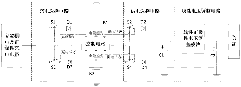
[0050] like figure 1 As shown, both the first DC battery B1 and the second DC battery B2 have positive polarity outputs, and the charging selection circuit includes a parallel charging switch S1 and a charging switch S3 that are both connected to the output of the charging circuit, and the charging switch S1 is connected to the anode of the diode D1. The cathode of the diode D1 is connected to the positive pole of the first DC battery B1 and one end of the power supply switch S2, the other end of the power supply switch S2 is connected to the anode of the diode D2, and the cathode of the diode D2 is connected to the input end of the linear voltage adjustment circuit and the positive pole of the electrolytic capacitor C1 , the negative pole of the electrolytic capacitor C1 is grounded; the negative pole of the first DC battery is grounded; the charging switch S3 is connected to the anode of the diode D3, the cathode of the diode D3 is connected to the positive pole of the secon...

Embodiment 2

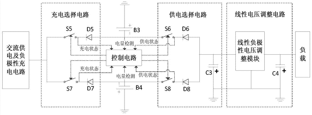
[0069] like figure 2 As shown, both the first DC battery B3 and the second DC battery B4 have negative polarity outputs, and the charging selection circuit includes a parallel charging switch S5 and a charging switch S7 that are both connected to the output of the charging circuit, and the charging switch S5 is connected to the cathode of the diode D5. The anode of the diode D5 is connected to the negative pole of the first DC battery B3 and one end of the power supply switch S6, the other end of the power supply switch S6 is connected to the cathode of the diode D6, and the anode of the diode D6 is connected to the input terminal of the linear voltage adjustment circuit and the negative pole of the electrolytic capacitor C3 , the positive pole of the electrolytic capacitor C3 is grounded; the positive pole of the first DC battery is grounded. The charging switch S7 is connected to the cathode of the diode D7, the anode of the diode D7 is connected to the negative pole of the...


PUM


Abstract

Provided is a direct-current power source low ripple wave implementation method with batteries supplying power continuously. The rechargeable and non-ripple-wave direct-current batteries supply power to a load through a linear voltage adjusting circuit, the number of the direct-current batteries is two, only one direct-current battery supplies power at the same moment, and the direct-current battery supplying power is not charged; if the other battery is full of power, the battery is in a standby state and otherwise, the battery is charged. The invention further provides corresponding implementation circuits, and the circuits comprise a charging circuit, a charging selection circuit, a control circuit, a first direct-current battery, a second direct-current battery, a power supplying selection circuit and the linear voltage adjusting circuit. According to the direct-current power source low ripple wave implementation method and the implementation circuits, inherent power frequency ripple waves of an alternating-current rectification circuit can be thoroughly eliminated, low ripple waves of a direct-current output power source are achieved, and continuous power energy supply of the direct-current power source is guaranteed.

Description

technical field [0001] The invention belongs to the field of precision measuring instruments, and is applied to occasions requiring an ultra-low ripple DC power supply, in particular to a method and circuit for realizing low ripple of a DC power supply continuously powered by a battery. Background technique [0002] Improving measurement accuracy is an important purpose of signal measurement. Reducing various errors is an important method to improve measurement accuracy. DC power supply ripple is one of the main sources of signal error. DC power supply can be divided into diode power frequency rectification stabilized power supply and switching power supply according to its working frequency. image 3 In the shown battery direct power supply and power frequency rectification power supply circuit, the ripple analysis is carried out on loads with nominal resistance values ​​of 45Ω, 90Ω, 180Ω and 1800Ω respectively on the two power supplies (nominal operating currents are 200mA,...

Claims


Application Information

Patent Timeline
Patent Type & Authority Patents(China)
IPC IPC(8): H02J7/00H02J9/06
Inventor 程为彬李彬
Owner XI'AN PETROLEUM UNIVERSITY
Why Eureka
Try Eureka