Three-phase PWM rectifier control method

A control method and ring control technology, applied in the direction of output power conversion device, AC power input conversion to DC power output, electrical components, etc., can solve the inconvenience of system implementation, the switching frequency is not fixed, and the switching frequency is not conducive to the AC side Reactance filter design and other issues

Active Publication Date: 2014-11-26
合肥庐阳科技创新集团有限公司
View PDF2 Cites 15 Cited by
  • Summary
  • Abstract
  • Description
  • Claims
  • Application Information

AI Technical Summary

Problems solved by technology

Since the direct power control method often adopts the double closed-loop design of the voltage feedback outer loop and the current feedback inner loop, and uses the power hysteresis loop to select the switch table, the switching frequency is not fixed, and the changing switching frequency is not conducive to the design of the AC side reactance filter.
At the same time, due to the high sampling period, high-speed A / D converters and processors are required for data acquisition and algorithm processing, which is not convenient for system implementation.

Method used


Image

  • Three-phase PWM rectifier control method
  • Three-phase PWM rectifier control method
  • Three-phase PWM rectifier control method

Examples


example 1

[0046] This example is a control process of a three-phase two-level PWM rectifier whose technical parameters are shown in Table 1 using the control method of the present invention. The present invention will be described in detail below in conjunction with the accompanying drawings.

[0047] parameter name

value

DC side capacitance

2010uF

Grid side inductance

3mH

Load Resistance

100Ω (power 2kW)

On-off level

6KHz

DC bus voltage

450V

Grid side line voltage

240V

[0048] Table 1

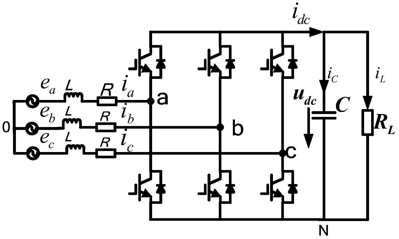
[0049] The main circuit structure of the three-phase two-level PWM rectifier controlled by the control method of the present invention is as follows: figure 1 Shown, where the electromotive force of the three-phase grid is e a 、e b 、e c , through the three-phase linear inductance L respectively connected to the connection of the upper and lower arms of the PWM rectifier bridge arm of each phase, the phase curren...

example 2

[0067] In order to verify the control performance of the control method provided by the present invention, this example compares the direct power control method with the double closed-loop design of the voltage feedback outer loop and current feedback inner loop described in the prior art with the control method adopted in Example 1 The three-phase two-level PWM rectifier whose technical parameters are shown in Table 1 are respectively controlled, and the model MSO-X3014A oscilloscope produced by the American Aglient company is used to collect the DC side of no-load startup, sudden load and on-load startup respectively. Voltage waveform, a-phase voltage and current waveform on AC side, d-axis grid side current component i in the two-phase rotating coordinate system d Waveform, the acquisition result is as follows Figure 4 with Figure 5 shown. control Figure 4 with Figure 5 It can be clearly seen that

[0068] Under no-load start-up conditions, refer to Figure 4 (a) ...


PUM


Abstract

The invention provides a three-phase PWM rectifier control method which includes a direct current capacitor energy storage outer loop control method and a grid-side current inner loop control method. The method includes the steps that direct current capacitor stored energy of a rectifier is fed back as a whole, given capacitor charging power is output after calculation is finished through an energy PI adjuster, grid-side input power is obtained by adding load power to the given capacitor charging power, a given grid-side d-axis current value i*d is obtained by dividing grid-side input power by the grid-side d-axis voltage component, a given q-axis current value i*q is obtained according to the relation between given d-axis current and given q-axis current, a grid-side voltage control value ud and a grid-side voltage control value uq are obtained in sequence according to the grid-side current inner loop control method, given voltage values are obtained through feedforward and decoupling of the ud, uq and the network voltage, given phase voltage output values are obtained through Park inverse transformation and Clark inverse transformation, and switch control signals Sa, Sb and Sc used for driving a PWM rectifier bridge arm electronic switch are obtained finally through space vector pulse width modulation. By means of the method, the dynamic response performance of a three-phase PWM rectifier can be improved greatly, and the method is particularly suitable for fast charging of electric cars and other occasions having high requirements for the response performance of the three-phase PWM rectifier.

Description

technical field [0001] The invention relates to the technical field of power electronics, in particular to a control method for a three-phase power electronic conversion device. Background technique [0002] Traditional rectifiers are composed of diodes or thyristors. This type of rectifier has disadvantages such as high input current harmonic content, low input power factor, one-way energy transfer, and uncontrollable DC side voltage. Since the late 1980s, PWM (Pulse Width Modulation, Pulse Width Modulation) technology has been introduced into rectifier control, and this high power factor PWM rectifier technology has become a research hotspot at home and abroad. Compared with the traditional rectification technology, the voltage source PWM rectification technology has the advantages of bidirectional flow of energy, controllable DC side voltage, low input current harmonics, high power factor, etc., and truly realizes "green power conversion". It is used in active power filt...

Claims


Application Information

Patent Timeline
Patent Type & Authority Applications(China)
IPC IPC(8): H02M7/217
Inventor 姜卫东李王敏胡杨佘阳阳吴志清赵德勇
Owner 合肥庐阳科技创新集团有限公司
Why Eureka
Try Eureka