A kind of control method of three-phase pwm rectifier
A control method and loop control technology, applied in the direction of output power conversion device, AC power input conversion to DC power output, electrical components, etc., can solve the problem that the switching frequency is not conducive to the design of the AC side reactance filter, the sampling period is high, and the It is convenient for system realization and other issues, and achieves the effect of improving dynamic response performance, adjusting time and reducing overshoot
- Summary
- Abstract
- Description
- Claims
- Application Information
AI Technical Summary
Problems solved by technology
Method used
Image
Examples
example 1
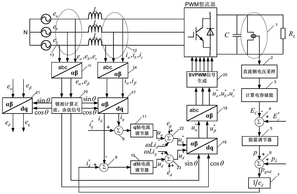
[0046] This example is a control process of a three-phase two-level PWM rectifier whose technical parameters are shown in Table 1 using the control method of the present invention. The present invention will be described in detail below in conjunction with the accompanying drawings.
[0047] parameter name value DC side capacitance 2010uF Grid side inductance 3mH Load Resistance 100Ω (power 2kW) operating frequency 6KHz DC bus voltage 450V Grid side line voltage 240V
[0048] Table 1
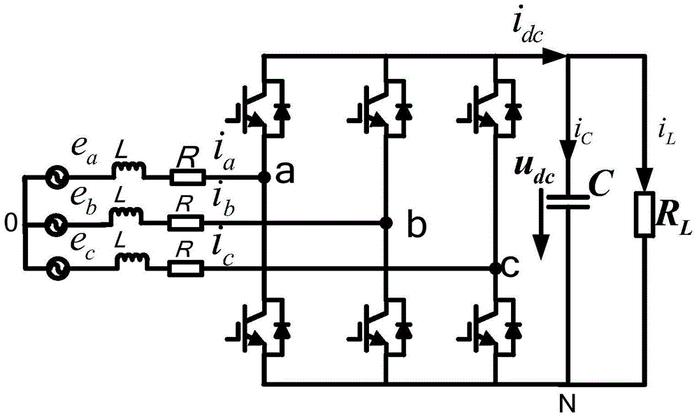
[0049] The main circuit structure of the three-phase two-level PWM rectifier controlled by the control method of the present invention is as follows: figure 1 Shown, where the electromotive force of the three-phase grid is e a 、e b 、e c , through the three-phase linear inductance L respectively connected to the connection of the upper and lower arms of the PWM rectifier bridge arm of each phase, the phase currents of the three-phase grid...
example 2
[0067] In order to verify the control performance of the control method provided by the present invention, this example compares the direct power control method with the double closed-loop design of the voltage feedback outer loop and current feedback inner loop described in the prior art with the control method adopted in Example 1 The three-phase two-level PWM rectifier whose technical parameters are shown in Table 1 are respectively controlled, and the model MSO-X3014A oscilloscope produced by the American Aglient company is used to collect the DC side of no-load startup, sudden load and on-load startup respectively. Voltage waveform, a-phase voltage and current waveform on AC side, d-axis grid side current component i in the two-phase rotating coordinate system d Waveform, the acquisition result is as follows Figure 4 and Figure 5 shown. control Figure 4 and Figure 5 It can be clearly seen that
[0068] Under no-load start-up conditions, refer to Figure 4 (a) an...
PUM
 Abstract
Description
Claims
Application Information
 - R&D
- Intellectual Property
- Life Sciences
- Materials
- Tech Scout
- Unparalleled Data Quality
- Higher Quality Content
- 60% Fewer Hallucinations
Browse by: Latest US Patents, China's latest patents, Technical Efficacy Thesaurus, Application Domain, Technology Topic, Popular Technical Reports.
© 2025 PatSnap. All rights reserved.Legal|Privacy policy|Modern Slavery Act Transparency Statement|Sitemap|About US| Contact US: help@patsnap.com


