
Electric wire holding structure

A wire retainer and wire retainer technology, which is applied in the direction of circuits, conductive connections, electrical components, etc., can solve the problems of wire retainer loosening and connection stability between wires and crimp terminals.

Inactive Publication Date: 2014-11-26
YAZAKI CORP
View PDF4 Cites 0 Cited by
  • Summary
  • Abstract
  • Description
  • Claims
  • Application Information

AI Technical Summary

Problems solved by technology

[0008] However, with the wire holding structure described in Patent Document 1, since there is a fitting gap between the engaging convex portion and the engaging concave portion, and the wire holder becomes loose due to vibration, as a result, there is a possibility that the connection of the electric wire to the crimp terminal is stable. problem of reduced sex

Method used


Image

  • Electric wire holding structure
  • Electric wire holding structure
  • Electric wire holding structure

Examples


Embodiment Construction

[0090] Next, embodiments of the electric wire holding structure according to the present invention will be specifically described with reference to the accompanying drawings.

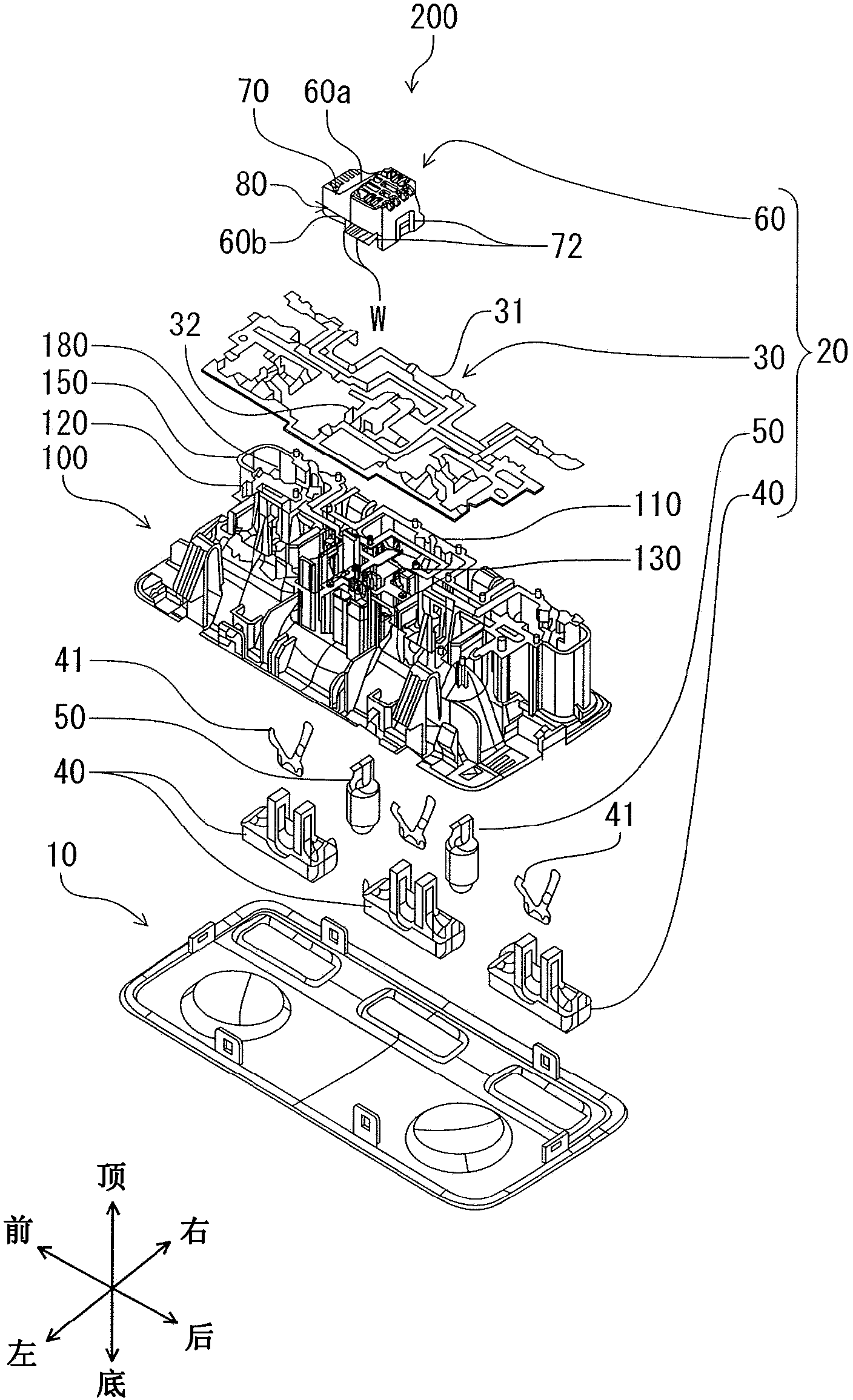
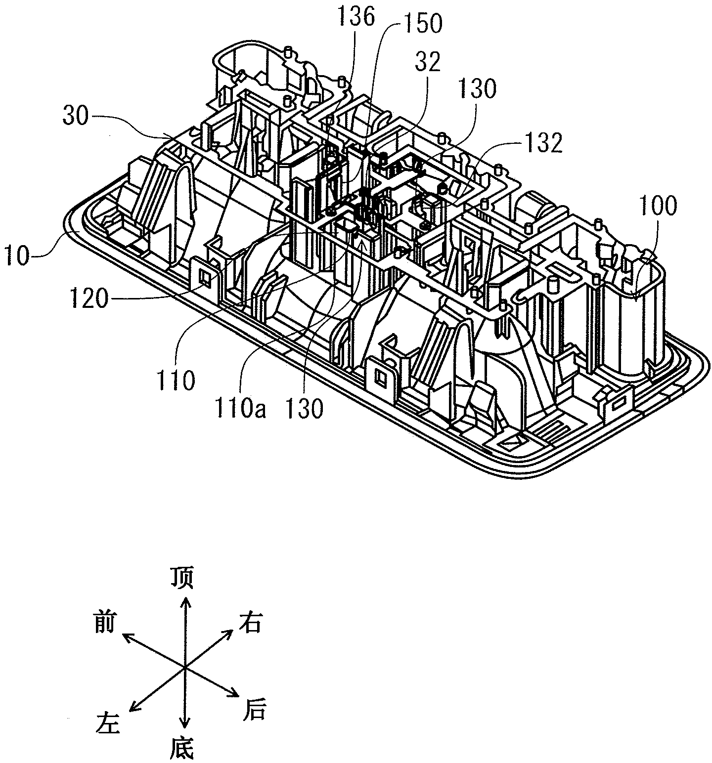
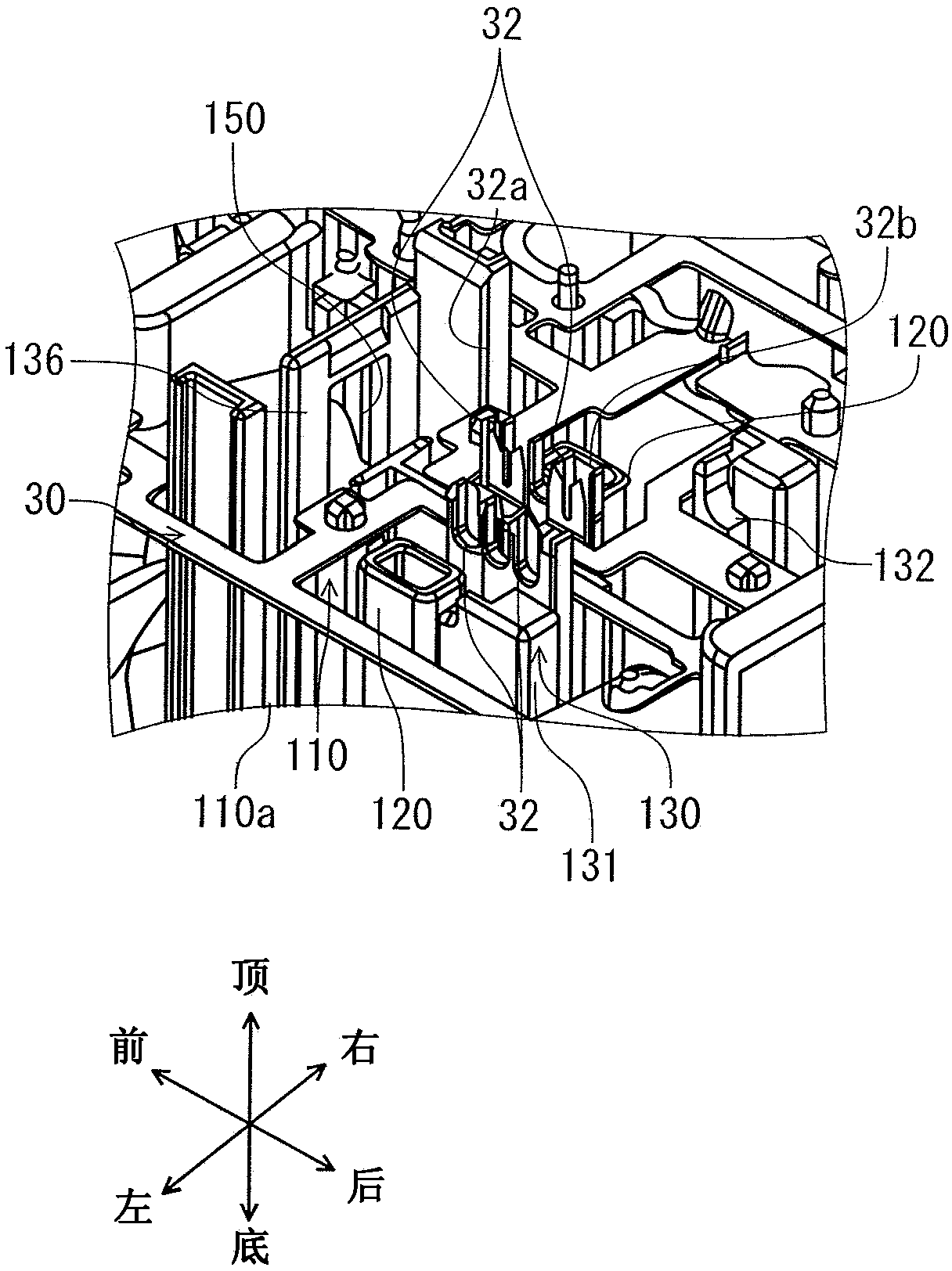
[0091] figure 1 is an exploded perspective view of the lighting device 200 including the wire holding structure 1 according to the embodiment of the present invention. figure 2 is loading figure 1 A perspective view of the lighting device 200 before the wire retainer 60 is shown. image 3 yes figure 2 An enlarged view of the area around the wire retainer attachment portion 110 is shown. Figure 4 yes image 3 A top view of the area around the wire retainer attachment portion 110 is shown. Figure 5 yes figure 1 An enlarged view of the wire retainer 60 is shown. Figure 6 is shown in figure 1 A perspective view of a state before the upper holding portion 70 of the wire holder 60 is overlaid on the lower holding portion 80 of the wire holder 60 is shown. Figure 7 is shown attaching the wire re...


PUM


Abstract

An electric wire holding structure includes an electric wire holder, an electric wire holder attached portion, and an engaging portion. The electric wire holder holds and arranges a part of a plurality of electric wire and includes a rotation shaft at one end in a direction perpendicular to an extending direction of the plurality of electric wires. The electric wire holder attached portion includes a shaft supporting portion which pivotally support the rotation shaft and a plurality of press contact terminals to which the electric wires are press contacted, and to which the electric wire holder is attached while being pivotally supported by the shaft supporting portions and being rotated. The engaging portion includes an convex engaging portion and a concave engaging portion or an engaging hole portion.

Description

technical field [0001] The present invention relates to an electric wire holding structure in which a plurality of electric wires are crimped to crimp terminals to be held. Background technique [0002] Conventionally, a wire holding structure in which a plurality of electric wires are crimped to crimp terminals to be held includes: a wire holder in which some of the plurality of electric wires are aligned and held; A wire holder attaching portion of a wire holder to which a wire is crimped and to which a wire holder is attached. When the wire holder is attached to the wire holder attaching portion, a plurality of wires are crimped to the crimp terminal and held in the wire holding structure. For example, in Patent Document 1, there is disclosed a wire holding structure capable of reducing the load required for crimping even when a plurality of wires are simultaneously crimped to a crimp terminal (see, for example, Patent Document 1). [0003] The electric wire holding st...

Claims


Application Information

Patent Timeline
Patent Type & Authority Applications(China)
IPC IPC(8): H01R43/01H01R9/24H01R4/24H01R13/631
CPCH01R9/2416H01R13/631H01R4/2445H02G1/00
Inventor 千叶真吾
Owner YAZAKI CORP
Learn More