Conveying mechanism for key cylinder

A technology of conveying mechanism and lock cylinder, which is applied in the direction of conveyor, transportation and packaging, can solve the problems of low work efficiency and troublesome operation, and achieve the effect of high work efficiency, low cost and compact structure.

Inactive Publication Date: 2014-12-03
WUXI ZHONGWANG 4D TECH
View PDF5 Cites 4 Cited by
  • Summary
  • Abstract
  • Description
  • Claims
  • Application Information

AI Technical Summary

Problems solved by technology

In the prior art, during the machining process of the lock cylinder, when the lock cylinder needs to be punched and slotted, in the assembly line processing, the workpiece is usually conveyed by a conveyor belt, and the workpiece is clamped and

Method used


Image

  • Conveying mechanism for key cylinder
  • Conveying mechanism for key cylinder
  • Conveying mechanism for key cylinder

Examples


Embodiment Construction

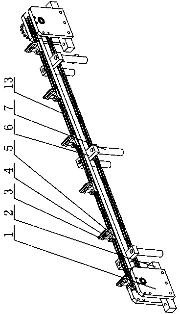
[0015] The specific implementation manner of the present invention will be described below in conjunction with the accompanying drawings.

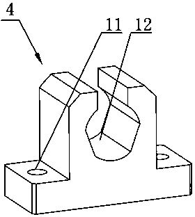
[0016] Such as figure 1 , figure 2 with image 3 As shown, the conveying mechanism for the lock core of the present embodiment includes bottom columns 2 arranged at intervals, support plates 1 are respectively installed on both sides of the bottom columns 2, sprockets are installed between the two support plates 1, and sprockets are installed between the two sprockets. The conveyor chain 13 is installed, and the conveyor chain 13 is fixed with a fixing device for installing the lock cylinder 3 at intervals. A base 4 is fixed, and the base 4 is in a convex shape. Both ends of the base 4 are provided with through holes 11 , and the middle part of the base 4 is provided with a U-shaped slot 12 for matching with the lock cylinder 3 .

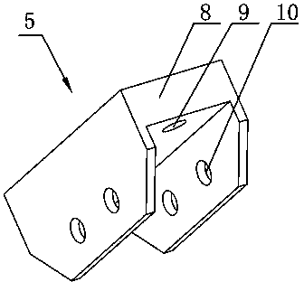
[0017] The structure of the card holder 5 is: there is a groove in the middle of the card holder 5, a fir...


PUM


Abstract

The invention relates to a conveying mechanism for a key cylinder. The conveying mechanism comprises sill pillars arranged at intervals, wherein supporting plates are mounted on the two sides of each sill pillar respectively; a chain wheel is mounted between every two supporting plates; a conveyer chain is mounted between the two chain wheels; fixing devices for mounting the key cylinder are fixed on the conveyer chain at intervals; each fixing device adopts the structure that the fixing device comprises a clamping seat; the clamping seats are fixed with the chain links of the conveyer chain through pins respectively; a base is fixed at the top of each clamping seat and adopts a convex-shaped structure; a through hole is formed in each of the two ends of each base; a U-shaped clamping groove matched with the key cylinder is formed in the middle part of each base. The conveying mechanism is compact and reasonable in structure, can fix the key cylinder onto the conveyer chain through the cooperating of the bases and the clamping seats, facilitates the automatic conveying of the key cylinder on a production line, and is good in operational reliability, high in working efficiency, and low in cost.

Description

technical field [0001] The invention relates to the technical field of conveying devices, in particular to a conveying mechanism for a lock cylinder. Background technique [0002] The lock cylinder is the main part that controls the opening of the lock. It is the heart of the lock. It refers to the core part that can be turned and driven by the key to move the lock. In the prior art, during the machining process of the lock cylinder, when the lock cylinder needs to be drilled and slotted, in the assembly line processing, the workpiece is usually conveyed by a conveyor belt, and the workpiece is clamped and punched when it is transported to a station. , Then continue to be transported to the next station for slotting, which is troublesome to operate and needs to be assembled and disassembled one by one by the staff, and the work efficiency is low. Contents of the invention [0003] Aiming at the shortcomings in the above-mentioned existing production technology, the applic...

Claims


Application Information

Patent Timeline
IPC IPC(8): B65G17/12
Inventor 董仲伟
Owner WUXI ZHONGWANG 4D TECH
Why Eureka
Try Eureka