Seabed ditching device

A technology of shell and shroud, applied in the direction of earth mover/shovel, construction, etc., can solve the problems of ditching failure, affecting the buried pipe, buried line, replacement, etc.

Active Publication Date: 2014-12-03
ZHANGJIAGANG HAIGONG SHIP MACHINERY MFGCO
View PDF6 Cites 5 Cited by
  • Summary
  • Abstract
  • Description
  • Claims
  • Application Information

AI Technical Summary

Problems solved by technology

This structure has the following disadvantages: 1. Since the coulter is used, the depth and width of the ditch cannot be too large due to the size of the coulter; It wears out, the coulters are easily damaged and need to be replaced frequently
3. The coulter will turn the mud and rocks in the ditch to both sides of the ditch when ditching, so that because the whole ditching device is moving, it is easy to generate water flow, so that the soil on both sides of the ditch will have a good ditch. Burial, resulting in trenching failure, affecting the subsequent buried pipe embedding

Method used


Image

  • Seabed ditching device

Examples


Embodiment Construction

[0019] The present invention will be described in further detail below through specific examples.

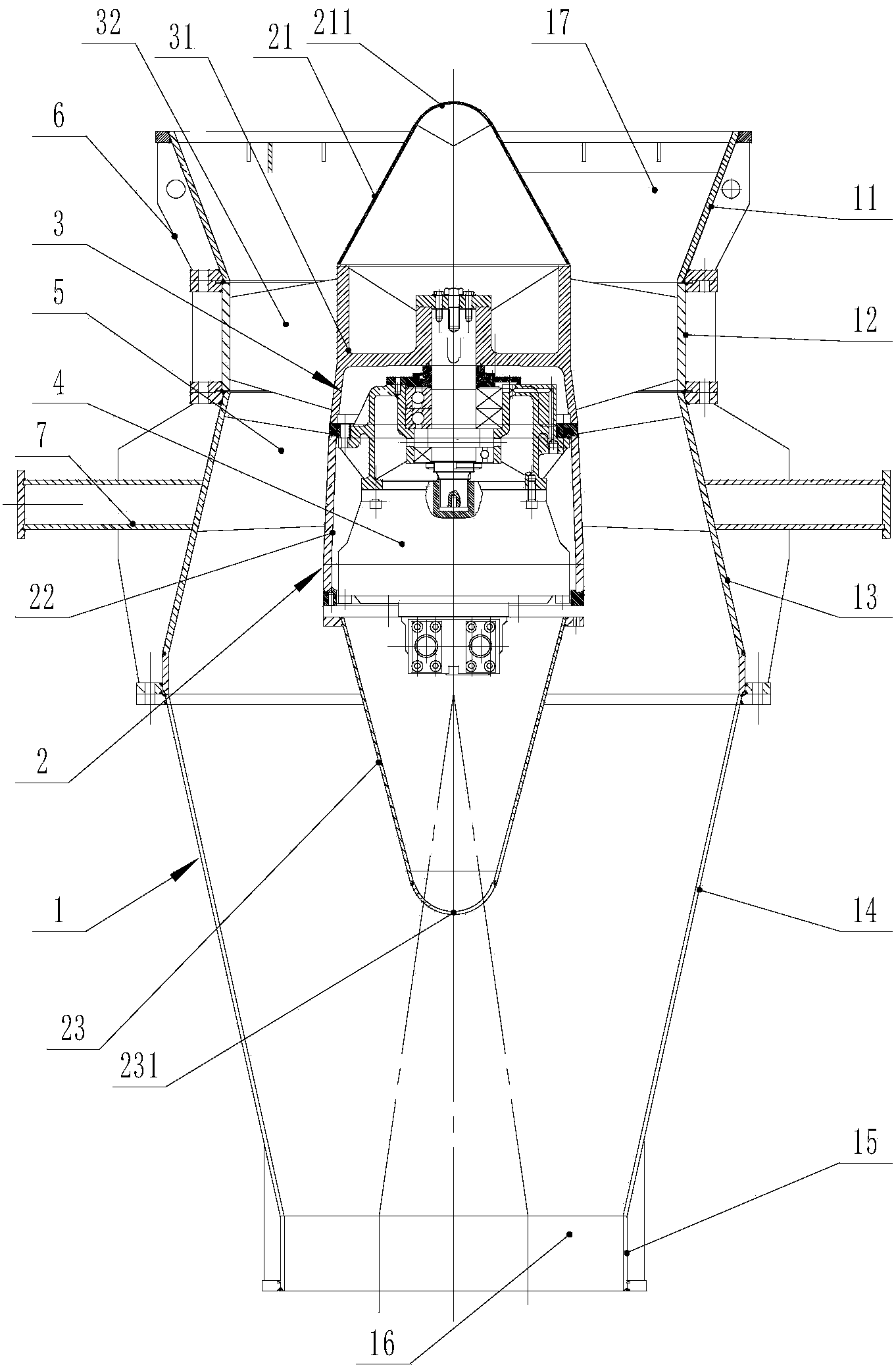
[0020] Such as figure 1 As shown, a subsea ditching device includes a frame and a ditching mechanism fixed on the frame. The ditching mechanism includes a casing 1, a hydraulic motor 4, an impeller 3 and a motor casing 2. The casing 1 is cylindrical , preferably cylindrical, one end of the shell 1 is the water inlet, the other end is the water outlet, the water inlet is provided with a water inlet 17, and the water outlet is provided with a water outlet 16, the size of the water outlet 16 is smaller than the water inlet 17 In this embodiment, the housing 1 includes a water inlet section 11, a connecting section 12, an expanding diameter section 13, a reducing diameter section 14 and a water outlet section 15. The water inlet section 11 is trumpet-shaped, and the connecting section 12 It is cylindrical, and the connecting section 12 connects the small-diameter end of the water i...


PUM


Abstract

The invention discloses a seabed ditching device which comprises a rack and two ditching mechanism identical in structure and fixed on the rack. Each ditching mechanism comprises a shell, a hydraulic motor, an impeller and a motor shell, each shell is tubular, one end of each shell is a water incoming end while the other end of the same is a water outgoing end, a water inlet is arranged at each water incoming end, a water outlet is arranged at each water outgoing end, size of each water outlet is smaller than that of the corresponding water inlet, each motor shell is fixed in an inner cavity of the corresponding shell, space between each motor shell and the corresponding shell forms a water flow passage, each hydraulic motor is fixed in the corresponding motor shell, each impeller is mounted on an output shaft of the corresponding hydraulic motor, blades of each impeller are positioned in the inner cavity of the corresponding shell, and each shell is provided with a suspending structure at the corresponding water incoming end. The seabed ditching device ditches seabed mudstone by utilizing rotating impact force of water flow, and excavated mudstone is mixed with seawater and needs some time to settle, so that sufficient time is acquired for pipe burying and wire burying. The seabed ditching device does not directly contact with the seabed mudstone, thereby being long in service life and high in ditching efficiency.

Description

technical field [0001] The invention relates to a deep-sea ditching device, in particular to a deep-sea automatic ditching device for laying submarine pipelines. Background technique [0002] The current seabed trenching device is carried out in the form of a furrow. Simply speaking, the current deep-sea trencher uses a marine vehicle to hang a frame through a cable. The frame is provided with a coulter. When in use, the frame Submerged to the bottom of the sea, the marine vehicle then provides a traction force to the frame so that the frame advances and the coulters perform a ditching action on the bottom of the sea. This structure has the following disadvantages: 1. Since the coulter is used, the depth and width of the ditch cannot be too large due to the size of the coulter; As it wears out, the coulters are easily damaged and need to be replaced frequently. 3. The coulter turns the mud and rocks in the ditch to both sides of the ditch when it is ditching, so that becau...

Claims


Application Information

Patent Timeline
Patent Type & Authority Applications(China)
IPC IPC(8): E02F5/02
Inventor 王金兴
Owner ZHANGJIAGANG HAIGONG SHIP MACHINERY MFGCO
Why Eureka
Try Eureka