
Split flow discarding filter device

A discarded flow filtration and split flow technology, applied in water supply devices, grease/oily substance/float removal devices, water/sludge/sewage treatment, etc. Low, low impulse, strong stability effect

Inactive Publication Date: 2017-08-25
SHANGHAI BIAONENG BUILDING TECH
View PDF10 Cites 0 Cited by
  • Summary
  • Abstract
  • Description
  • Claims
  • Application Information

AI Technical Summary

Problems solved by technology

[0007] In order to overcome the technical problems of troublesome removal of sediment inside the filter device and high cost of use in the prior art, the inventor has completed the present invention after conducting a large amount of in-depth research.

Method used


Image

  • Split flow discarding filter device
  • Split flow discarding filter device

Examples


Embodiment 1

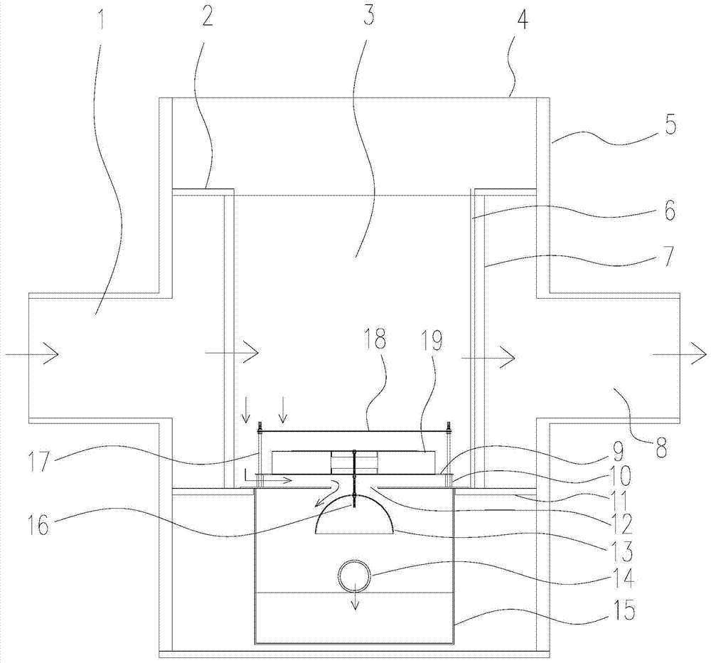
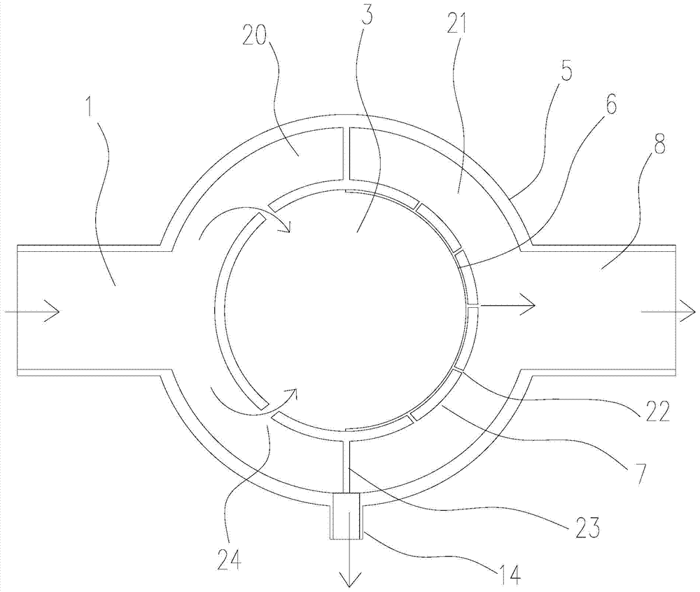
[0020] Such as figure 1 and figure 2 A shunt type discarding filter device shown includes an outer cylinder 5, an inner cylinder 7, a hanging cylinder 15 and a float valve 19, and the inner cylinder 7 is welded and fixed on the inner wall of the outer cylinder 5 through the upper partition 2 and the lower partition 11 , the upper partition 2 can prevent unfiltered rainwater from overflowing into the outer cavity, the lower partition 11 can place the hanging tube 15, the inner tube 7 and the outer tube 5 can be made of plastic materials, such as PE plastic or UPVC plastic, and the outer tube The two sides of 5 are provided with water inlet 1 and water outlet 8, and the water inlet 1 and water outlet 8 are connected with the outer cylinder 5 in a detachable manner such as threaded way, and the water inlet is connected to the sewage interception equipment, and the rainwater passes through the sewage interception equipment. The water inlet enters, and the water outlet 8 is conne...

Embodiment 2

[0023]The difference between this embodiment and Embodiment 1 is that the top of the stabilizing bar 17 is fixed with a steady flow plate 18, and the steady flow plate 18 is located above the float valve 19, the two are not in direct contact, the steady flow plate can be circular or For other shapes, as long as it is not smaller than the float valve, the rainwater falling down from both sides will not directly hit the light float valve below, effectively stabilizing the float valve.


PUM


Abstract

The invention relates to a shunting type discarding flow filter device which comprises an outer cylinder, an inner cylinder, a hanging cylinder and a float valve, wherein the inner cylinder is fixed on the inner wall of the outer cylinder through an upper partition board and a lower partition board; a water inlet and a water outlet are formed in two sides of the outer cylinder; stabilizer bars are arranged on two sides of the top end of the hanging cylinder; the float valve is nested on the stabilizer bars through a stainless steel board in a penetrating manner; a center hole and a discarding flow port are formed in the hanging cylinder; the float valve is connected with a half-ball valve through a connecting rod; a medium partition board for dividing space between the outer cylinder and the inner cylinder into a front outer cavity and a rear outer cavity is arranged between the outer cylinder and the inner cylinder; and shunting holes and water permeating holes are formed in two sides of the inner cylinder respectively. According to the shunting type discarding flow filter device, pollutants can be separated in time, a filter system is prevented from being blocked by impurities and suspended matters in rainwater, the filter efficiency at the later period when the rain is heavier is guaranteed, besides, the device is simple in structural design, low in cost, high in stability and simple to operate, and the pollutants are convenient to clean.

Description

technical field [0001] The invention relates to a rainwater filter device, in particular to a split flow discarded flow filter device. Background technique [0002] During the falling process of rainwater, dissolved gases, dissolved or suspended solids, heavy metals and bacteria in the air will enter into it. The pollutants in the surface runoff mainly come from the erosion of the surface by rainfall, so the surface sediment is the pollution in the surface runoff. The composition of surface sediments determines the nature of surface runoff pollution. Surface sediments include many pollutants, including solid waste debris (municipal waste, animal manure, accumulations at urban construction sites), chemicals (fertilizers and pesticides applied to lawns), vehicle emissions, etc. The surface with different land use functions The origin of its deposits varies. Therefore, the quality of rainwater varies with location and time. However, with the continuous development of urbaniz...

Claims


Application Information

Patent Timeline
Patent Type & Authority Patents(China)
IPC IPC(8): E03F5/14E03F3/04
Inventor 王金泉于孝坤程鹏王静
Owner SHANGHAI BIAONENG BUILDING TECH
Learn More