Pipe body flat clamp for spacing, limiting, fixing and clamping pipe body

A technology for limiting and fixing pipes, which is applied in the direction of pipes/pipe joints/fittings, pipe supports, mechanical equipment, etc., to achieve the effects of high mechanical strength, uniform force, and long service life

Inactive Publication Date: 2014-12-03
王国平
View PDF1 Cites 6 Cited by
  • Summary
  • Abstract
  • Description
  • Claims
  • Application Information

AI Technical Summary

Problems solved by technology

It can effectively overcome the quality and safety hazards caused by the fall of the pipe body caused by the unreliable fixing and clamping of the pipe body

Method used


Image

  • Pipe body flat clamp for spacing, limiting, fixing and clamping pipe body
  • Pipe body flat clamp for spacing, limiting, fixing and clamping pipe body
  • Pipe body flat clamp for spacing, limiting, fixing and clamping pipe body

Examples


Embodiment 1

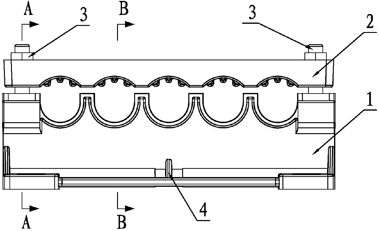
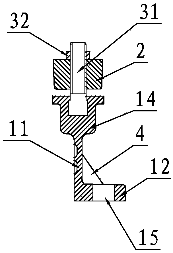
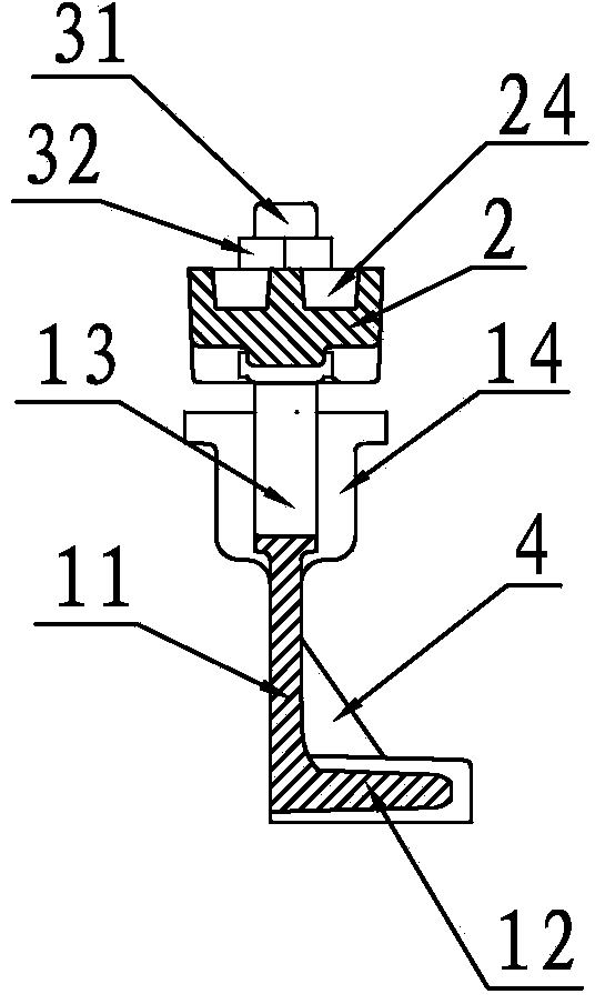
[0031] Embodiment 1: A kind of pipe body clamping that is fixedly clamped at intervals between pipe bodies, such as Figure 1 to Figure 5As shown, it includes a tube clip 1, a tube body pressure plate 2, a fixing screw 31 and a nut 32. The tube clip 1 is composed of a spacer web 11 and a fixed bottom plate 12, and is spaced along the length direction on the spacer web 11. There are five U-shaped limiting grooves 13 for accommodating gas pipes, and fixing seats 14 are provided at both ends of the spacer web 11, and fixed screws 31 are inlaid on the fixing seats 14, and the fixed bottom plate 12 is arranged on the spacer web. 11, the installation bottom surface of the fixed base plate 12 is parallel to the axis of the limit groove 13, the angle between the spacer web plate 11 and the fixed base plate 12 is 90°, and there are fixed holes 15 at both ends of the fixed base plate 12. In order to fix the tube holder 1 on the wall, there is a water outlet hole 16 in the middle of the ...

Embodiment 2

[0032] Embodiment 2: A pipe body clamping arrangement for fixed clamping of the pipe body at intervals, including a pipe clamp seat 1, a pipe body pressure plate 2, a fixing screw 31 and a nut 32, and the tube clamp seat 1 is composed of a tube spacer web 11 Composed of a fixed bottom plate 12, ten U-shaped limiting grooves 13 for accommodating gas pipes are arranged at intervals along the length direction on the spacer web 11, and at both ends of the spacer web 11 and the fifth and sixth limit slots There is a fixed seat 14 between the grooves 13, and a fixed screw 31 is inlaid on the fixed seat 14. The angle between the spacer web 11 and the fixed bottom plate 12 is 90°. On the fixed bottom plate 12, three Fixing holes 15, one at each end and one in the middle, are used to fix the tube holder 1 on the wall, and there are three water outlet holes 16 at equal intervals at the junction of the spacer panel 11 and the fixed bottom plate 12, for timely drainage. Rainwater; ten arc...


PUM


Abstract

The invention discloses a pipe body flat clamp for spacing, limiting, fixing and clamping a pipe body. The pipe body flat clamp comprises a pipe clamping seat and a pipe body pressing plate formed by adopting an SMC composite material through die pressing, wherein limiting grooves and fixing seats are arranged on the pipe-separating center plate of the pipe clamping seat at intervals; pipe bodies to be fixed are arranged among the limiting grooves and the pipe body pressing plate respectively; the pipe body pressing plate is connected with the pipe clamping seat through fastening components, so that the separated limiting and reliable pressing of the pipe bodies to be fixed are realized, and the virtual pressing of the pipe bodies are eradicated. According to the pipe body flat clamp, as the pipe clamping seat is designed into the support structure consisting of the pipe-separating center plate and a fixing baseplate, the limiting grooves for accommodating the pipe bodies to be fixed are formed in the pipe-separating center plate, fixing seats are arranged at the two ends of the pipe-separating center plate, fixing screws are embedded into the fixing seats, the fixing baseplate is fixed onto a wall, and the pipe body pressing plate is mounted on the screws in a sleeving manner and is tightened through nuts, the clamp adopting the structure is convenient to disassemble, and extremely convenient; moreover, as the pipe clamping seat and the pipe body pressing plate adopting the composite material are formed through the die pressing, the pipe body flat clamp is good in mechanical strength property, thermal stability property, corrosion resistance property and cold resistance property, and is long in service life.

Description

Technical field: [0001] The invention relates to the technology of gas pipes, water pipes and other pipes entering the house along the wall, in particular to a pipe clamping device for fixing the pipe body. Background technique: [0002] Running water and natural gas are indispensable to modern family life, and natural gas, as the main energy source of modern life, has brought great convenience to modern life. With the development of society, natural gas has been popularized to thousands of households. Environmental protection, safety, speed and convenience have become the standard and trend of urban gas supply projects. The gas pipeline network supply project has very high requirements on construction quality, and the pipeline of gas supply is one of the important symbols of modern cities. The construction of the gas pipeline network is divided into two parts: the outdoor pipeline network and the indoor pipeline network. The outdoor pipeline network is mostly buried, whic...

Claims


Application Information

Patent Timeline
Patent Type & Authority Applications(China)
IPC IPC(8): F16L3/10
CPCF16L3/2235
Inventor 王国平
Owner 王国平
Why Eureka
Try Eureka