
A moving coil for an angular vibrating table

A technology of angular vibration table and moving coil, which is applied in the direction of coils, instruments, electrical components, etc., can solve the problems of poor directionality of the output torque of the moving coil, low efficiency of motor-machine conversion, and low first-order natural frequency, so as to improve the natural frequency , Increase the number of effective wire segments, the effect of small moment of inertia

Active Publication Date: 2017-04-12
ZHEJIANG UNIV
View PDF1 Cites 0 Cited by
  • Summary
  • Abstract
  • Description
  • Claims
  • Application Information

AI Technical Summary

Problems solved by technology

[0007] In order to overcome the existing moving coil structure, it is necessary to open a skeleton slot to position the wires, resulting in low stiffness of the moving coil, low first-order natural frequency, poor directionality and uniformity of the output torque of the moving coil due to manual winding, and low motor-to-machine conversion efficiency. Disadvantages, the present invention provides a moving coil of an angular vibrating table that can make the coil winding uniform without opening a wire slot

Method used


Image

  • A moving coil for an angular vibrating table
  • A moving coil for an angular vibrating table
  • A moving coil for an angular vibrating table

Examples


Embodiment Construction

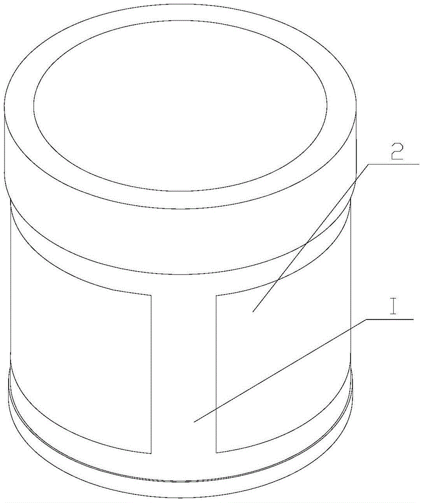
[0026] Such as figure 1 As shown, a moving coil of an angular vibrating table includes a moving coil base body 2 and a driving coil I, and the driving coil I covers the outer surface of the moving coil base body 2 .

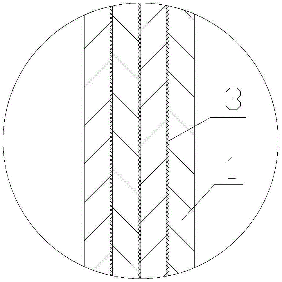
[0027] Such as figure 2 As shown, the driving coil 1 includes a coil winding 1 and an insulating layer 3, the coil winding 1 and the insulating layer 3 are arranged at intervals, the coil winding 1 has at least one layer, the insulating layer 3 is made of epoxy resin glue and glass cloth, and the insulating layer 3 Completely covers the coil winding 1 inside it.

[0028] Such as image 3 As shown, each coil winding includes a first coil 1-1 and a second coil 1-2, the first coil 1-1 is wound counterclockwise from inside to outside, and the second coil 1-2 is clockwise wound from outside to inside, The first coil 1-1 and the second coil 1-2 are on the same layer, and the first coil 1-1 and the second coil 1-2 are respectively wound with multiple turns, and each...


PUM


Abstract

The invention provides a moving coil of an angular vibration table. The moving coil comprises a moving coil base body and a driving coil. The outer side face of the moving coil base body is covered with the driving coil. The driving coil comprises coil windings and insulating layers, wherein the coil windings and the insulating layers are arranged alternately, the number of the coil windings is at least one layer, and the insulting layers completely cover the coil windings in the insulating layers. Each coil winding comprises a first coil and a second coil, wherein the first coil is wound anticlockwise from inside to outside, the second coil is wound clockwise from outside to inside, the first coil and the second coil are located on the same layer, the first coil and the second coil are wound respectively in multiple turns, each turn of the coil is composed of effective wire sections and connecting wire sections, the electrified effective wire sections generate ampere force in a magnetic field, and the connecting wire sections are located outside the magnetic field; the effective wire sections form an ampere force generation part. The space between all turns of wires of the coil windings is filled with epoxy resin glue, and the coil windings are connected with one another in series or in parallel. The moving coil of the angular vibration table has the advantages that the coils can be wound evenly with no need to form wiring grooves.

Description

technical field [0001] The invention relates to a motion component of an angular vibrating table, in particular to a moving coil of an angular vibrating table. [0002] technical background [0003] The electromagnetic vibrating table provides the vibration source for the vibration measurement calibration device or the vibration test device. The working principle of the electromagnetic vibrating table is based on the Ampere's law that the energized conductor is subjected to electromagnetic force in the air gap magnetic field. The moving coil wire is wound on the moving coil base. The moving coil part of the vibrating table, therefore, the wiring method of the moving coil part, the effective length of the wire, the size and shape of the wire directly affect the motion mode of the vibrating table (linear motion or rotary motion) and the thrust or torque. [0004] Angular vibration (angular displacement, angular velocity, angular acceleration) sensors are widely used in aerospac...

Claims


Application Information

Patent Timeline
Patent Type & Authority Patents(China)
IPC IPC(8): G01D18/00H01F5/00
Inventor 何闻唐波贾叔仕周杰
Owner ZHEJIANG UNIV
Learn More