Test device and method for measuring binding force between ice and asphalt pavement in multiple angles

A technology of asphalt pavement and test equipment, which is applied in the direction of measuring devices, instruments, and mechanical devices, etc. It can solve the problems of not being able to bear multiple force angles, measuring the adhesion between ice and snow and asphalt pavement, and only measuring the straight-pull adhesion. , to achieve a comprehensive and reliable evaluation

Active Publication Date: 2014-12-03
HARBIN INST OF TECH
View PDF5 Cites 10 Cited by
  • Summary
  • Abstract
  • Description
  • Claims
  • Application Information

AI Technical Summary

Problems solved by technology

[0005] The present invention aims to solve the problem that the existing equipment is only limited to measuring the straight-pull bonding force, cannot measure the bonding force between ice and snow and asphalt pavement at multiple stres

Method used


Image

  • Test device and method for measuring binding force between ice and asphalt pavement in multiple angles
  • Test device and method for measuring binding force between ice and asphalt pavement in multiple angles
  • Test device and method for measuring binding force between ice and asphalt pavement in multiple angles

Examples


specific Embodiment approach 1

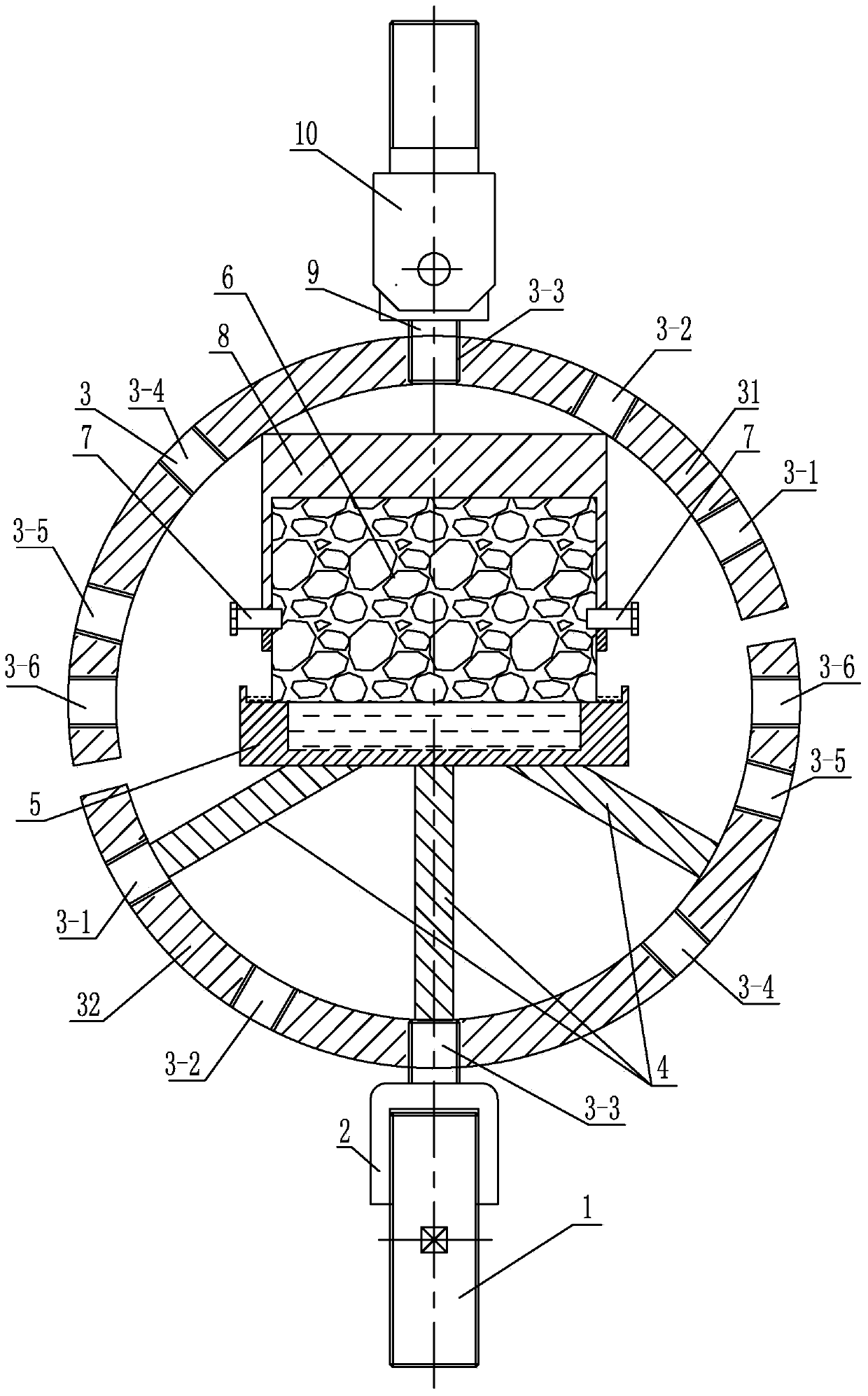
[0025] Specific implementation mode one: combine Figure 1-Figure 14 Illustrate, a kind of multi-angle test equipment of measuring ice and asphalt pavement cohesive force of the present embodiment comprises cylindrical container 8, hollow groove 5, connection assembly, two ring brackets and three struts 4;

[0026] The connecting assembly includes a lower connecting screw 1, a lower connecting sleeve 2, an upper connecting ear 9 and an upper connecting screw 10; the hollow groove 5 includes a hollow cylinder 5-1 and a ring 5-2, and the hollow cylinder 5-1 The open end of the ring 5-2 is connected, and the outer peripheral side of the hollow cylinder 5-1 is flush with the outer peripheral side of the ring 5-2;

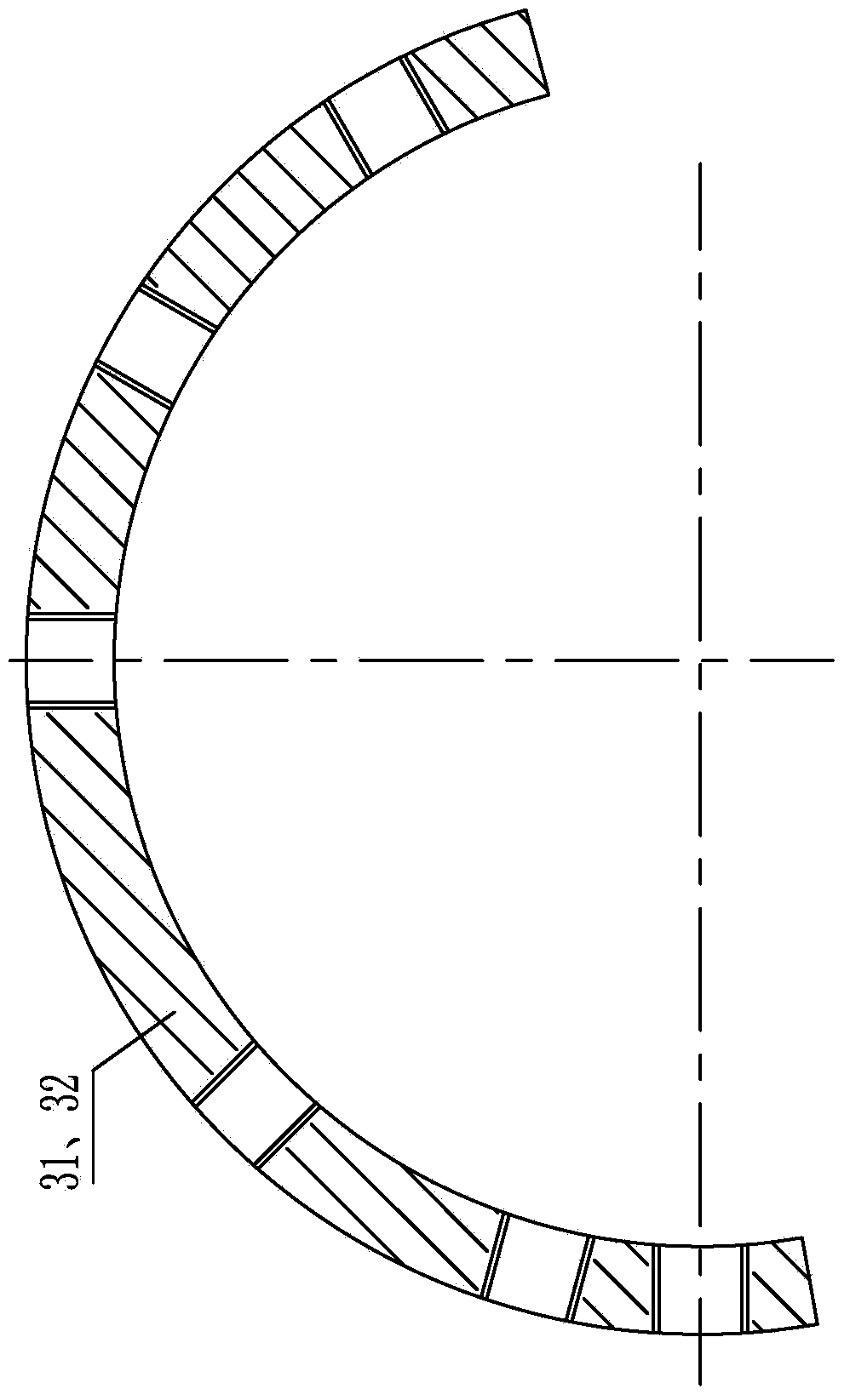
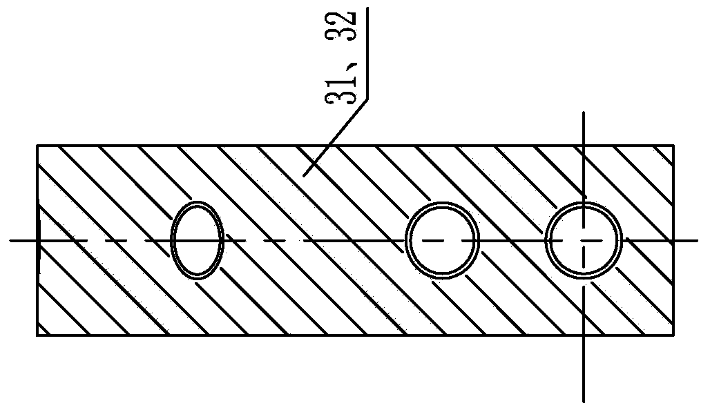
[0027] The two ring holders are respectively an upper ring holder 31 and a lower ring holder 32. The upper ring holder 31 and the lower ring holder 32 are arc-shaped, and the peripheral sides of the upper ring holder 31 and the lower ring holder 32 are each processed with...

specific Embodiment approach 2

[0032] Specific implementation mode two: combination Figure 1-4 Note that the upper ring holder 31 and the lower ring holder 32 of this embodiment are both stainless steel ring holders. With such a setting, the strength is high, which meets the needs of the actual test. Others are the same as in the first embodiment.

specific Embodiment approach 3

[0033] Specific implementation mode three: combination Figure 1-4 Note that the central angles of the upper ring support 31 and the lower ring support 32 of this embodiment are both 175°. With such arrangement, the arc length of the ring bracket is long and the strength is high. Others are the same as in the first or second embodiment.


PUM

PropertyMeasurementUnit
Central angleaaaaaaaaaa
Overall heightaaaaaaaaaa
Outer diameteraaaaaaaaaa

Abstract

The invention relates to a test device and method for measuring a binding force between ice and an asphalt pavement in multiple angles, and aims at solving the problems that the existing device is limited for measuring the direct-pull binding force and cannot measure the binding force between ice and snow and the asphalt pavement in multiple angles, and a method for measuring the binding state between the ice and the pavement under the effect of vehicles cannot be provided. The test device comprises a cylindrical vessel, a hollow trough, a connection assembly, two ring carriers and three supporting rods, wherein the connection assembly comprises a lower connection screw, a lower connection sleeve, an upper connection lug and an upper connection screw; the hollow trough comprises a hollow cylinder and a circular ring; the two ring carriers are respectively an upper ring carrier and a lower ring carrier, and the cylindrical vessel, the hollow trough and the three supporting rods are arranged in the circular ring. The test device and method are used for measuring the binding force between a mixture of the pavement and the ice.

Description

technical field [0001] The invention relates to a test equipment and method for measuring the adhesion force between ice and road surface, in particular to a test equipment and test for measuring the degree of adhesion between ice or ice-snow mixture attached to the surface of asphalt road at multiple stress angles method. Background technique [0002] In the cold winter, the snow and ice on the road will have a serious adverse effect on the smoothness of the road and driving safety, and cause great economic losses. In order to ensure the safety of driving on roads under icy and snowy weather, the transportation departments of various countries have explored a variety of methods of deicing and snow and a variety of methods of suppressing snow and ice on the road to slow down the impact of snow and ice. The cohesive force between the ice and the road surface directly affects the adhesion coefficient of the road surface, which directly determines the ice and snow removal abil...

Claims


Application Information

Patent Timeline
IPC IPC(8): G01N19/04
Inventor 谭忆秋王潇婷徐慧宁李云良吴思刚傅锡光周细威
Owner HARBIN INST OF TECH
Why Eureka
Try Eureka