A thermal conductivity measurement device based on steady state method

A thermal conductivity and measuring device technology, which is applied in the field of measuring devices for measuring thermal conductivity of materials by a steady-state method, can solve problems such as temperature measurement uncertainty errors, reduce measurement accuracy, and affect measurement accuracy, so as to improve measurement accuracy, The effect of reducing measurement error and avoiding lateral loss

Inactive Publication Date: 2017-02-15
UNIV OF ELECTRONICS SCI & TECH OF CHINA
View PDF2 Cites 0 Cited by
  • Summary
  • Abstract
  • Description
  • Claims
  • Application Information

AI Technical Summary

Problems solved by technology

This kind of structure, one. Although it overcomes the disadvantages of heat flow loss and affecting the accuracy of the measurement when the two contact interfaces of the sample to be tested in the previous background technology are overcome, the structure is too complicated, and the disassembly and installation before and after the measurement are difficult. Difficult disadvantages; two. when the tester measures, the surroundings of the test piece are exposed in the space, and when the heat flows through the test piece, due to the temperature gradient between the test piece and the surrounding environment, the heat flow is inevitably transmitted along the lateral direction, resulting in Uncertainty errors in temperature measurement are reduced, which not only reduces the accuracy of measurement, but also has poor consistency of measurement data; thirdly, the heating module is located in the upper part of the device, and the water cooling head is placed at the bottom of the device, which is still not conducive to heat along the test piece. Axial downward transmission, when the water flows through the water cooling head, the low temperature water is located at the bottom and affects the heat dissipation capacity, and when the temperature of the heat source "heating rod" is high, it is impossible to ensure that the ideal temperature gradient is formed between the heat source end and the cold end , coupled with unreasonable thermocouple settings (only at both ends) also affects the accuracy of measurement

Method used


Image

  • A thermal conductivity measurement device based on steady state method
  • A thermal conductivity measurement device based on steady state method
  • A thermal conductivity measurement device based on steady state method

Examples


Embodiment Construction

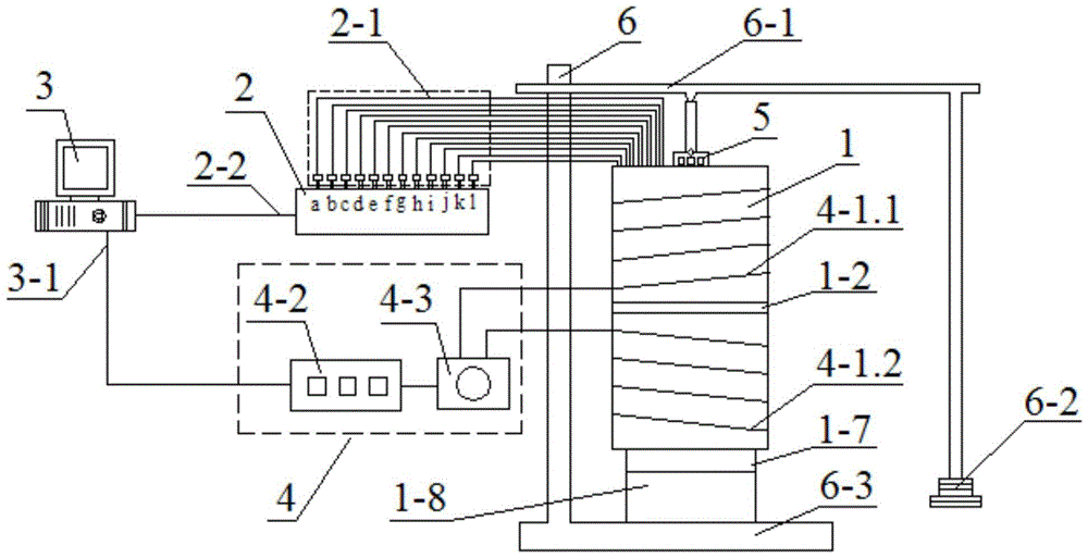
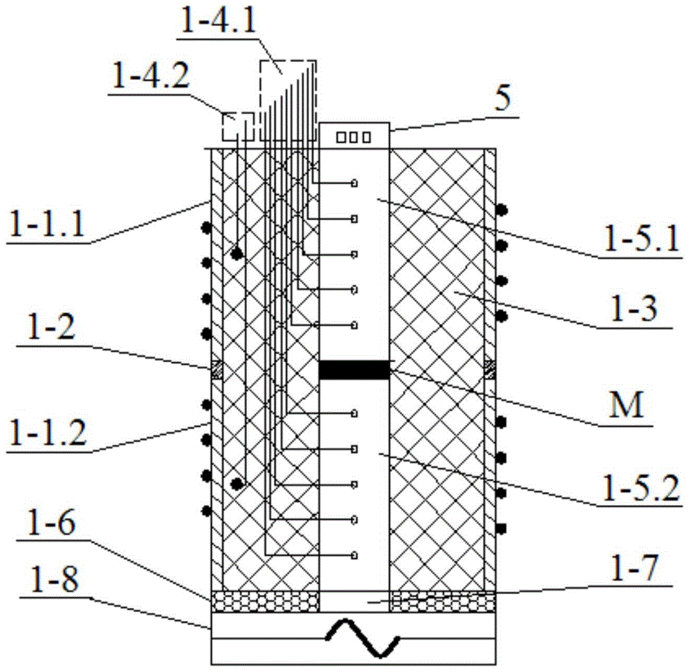
[0016] In this embodiment, the main heater 1-8 adopts an electric furnace, and the vapor chamber 1-7 is made of pure copper, surrounded by hard foam 1-6 as a heat insulation layer; the upper and lower standard test pieces 1-5.1 and 1-5.2 are implemented in this embodiment. The method adopts pure aluminum with a thermal conductivity of 237W / (K m), which are all cylinders with a diameter of Φ25mm and an axial height of 60mm. On each of them, 5 holes with a diameter of Φ1.1mm are drilled at a small interval of 10mm and a depth of 12.5mm. A small hole with a diameter of about 1.1mm and a depth of 12.5mm, with a pitch of 10mm, is used as a fixing hole for the thermocouple 1-4.1, and the thermocouple 1-4.2 is provided in the middle of the upper and lower shells at a distance of 5mm from the inner wall of the shell. 1-4.1 and 1-4.2 all use armored K-type thermocouple WRNK-191, with a diameter of 1mm, capable of measuring the temperature range of 0-1100°C, and each thermocouple is conn...


PUM


Abstract

The invention belongs to a steady-state method thermal conductivity measuring device in the technical field of material physical performance testing. Including the main heater, the upper and lower standard test pieces and the test piece placement cavity, the insulation layer, the upper and lower shells and the heat insulation ring between them, the heating wire connected by the heating wire with the temperature compensation regulator, The heating device of the thermocouple set in the upper and lower standard test pieces and in the insulation layer, the micro-channel cooling device, the temperature collector and the processing controller are composed of a column and a bottom plate, a lever with a pressure head in the middle and a weight Pressurization and fixing frame. Because the invention adopts an integral heating device, electric heating wires connected with temperature compensation regulators are respectively added on the upper and lower casings, and the main heater and microchannel radiator are respectively arranged at the bottom and top. Therefore, it has the characteristics of high precision in the measurement of thermal conductivity of materials by heating, good consistency in the results of repeated measurements, high stability, wide measurement range, and measurement under different heating conditions.

Description

technical field [0001] The invention belongs to the technical field of physical performance testing of materials, and in particular relates to a measuring device for measuring thermal conductivity of materials by a steady-state method (comparison method) including microchannel cooling and temperature compensation. [0002] Background technique: [0003] Thermal conductivity is widely used in electronics and other industries, and it is an indispensable basic data in engineering thermal design. Any electronic device and circuit will inevitably be accompanied by heat generation during the working process. With the improvement of packaging density of microelectronic devices, the energy consumption of chips is getting higher and higher. In order to enhance the heat dissipation capacity of devices and improve the reliability and electrical performance of electronic products, the generated heat must be released quickly and effectively. Radiator And thermal interface materials should...

Claims


Application Information

Patent Timeline
Patent Type & Authority Patents(China)
IPC IPC(8): G01N25/20
Inventor 徐尚龙郭宗坤王伟杰蔡奇彧
Owner UNIV OF ELECTRONICS SCI & TECH OF CHINA
Why Eureka
Try Eureka