Three-dimensional hall sensor for detecting a spatial magnetic field

A Hall sensor, space magnetic field technology, applied in the size/direction of the magnetic field, the geometrical arrangement of the magnetic sensor elements, the measurement of magnetic variables, etc., can solve the problem of lack of symmetry, and achieve the effect of simplifying the connection

Active Publication Date: 2014-12-03
TDK MICRONAS 有限公司
View PDF11 Cites 13 Cited by
  • Summary
  • Abstract
  • Description
  • Claims
  • Application Information

AI Technical Summary

Problems solved by technology

The root cause is the lack of symmetry of the structure

Method used


Image

  • Three-dimensional hall sensor for detecting a spatial magnetic field
  • Three-dimensional hall sensor for detecting a spatial magnetic field
  • Three-dimensional hall sensor for detecting a spatial magnetic field

Examples


Embodiment approach

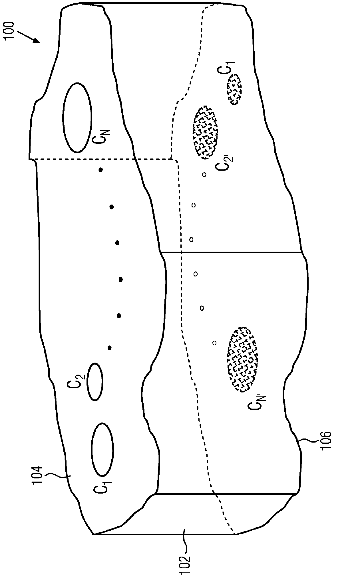
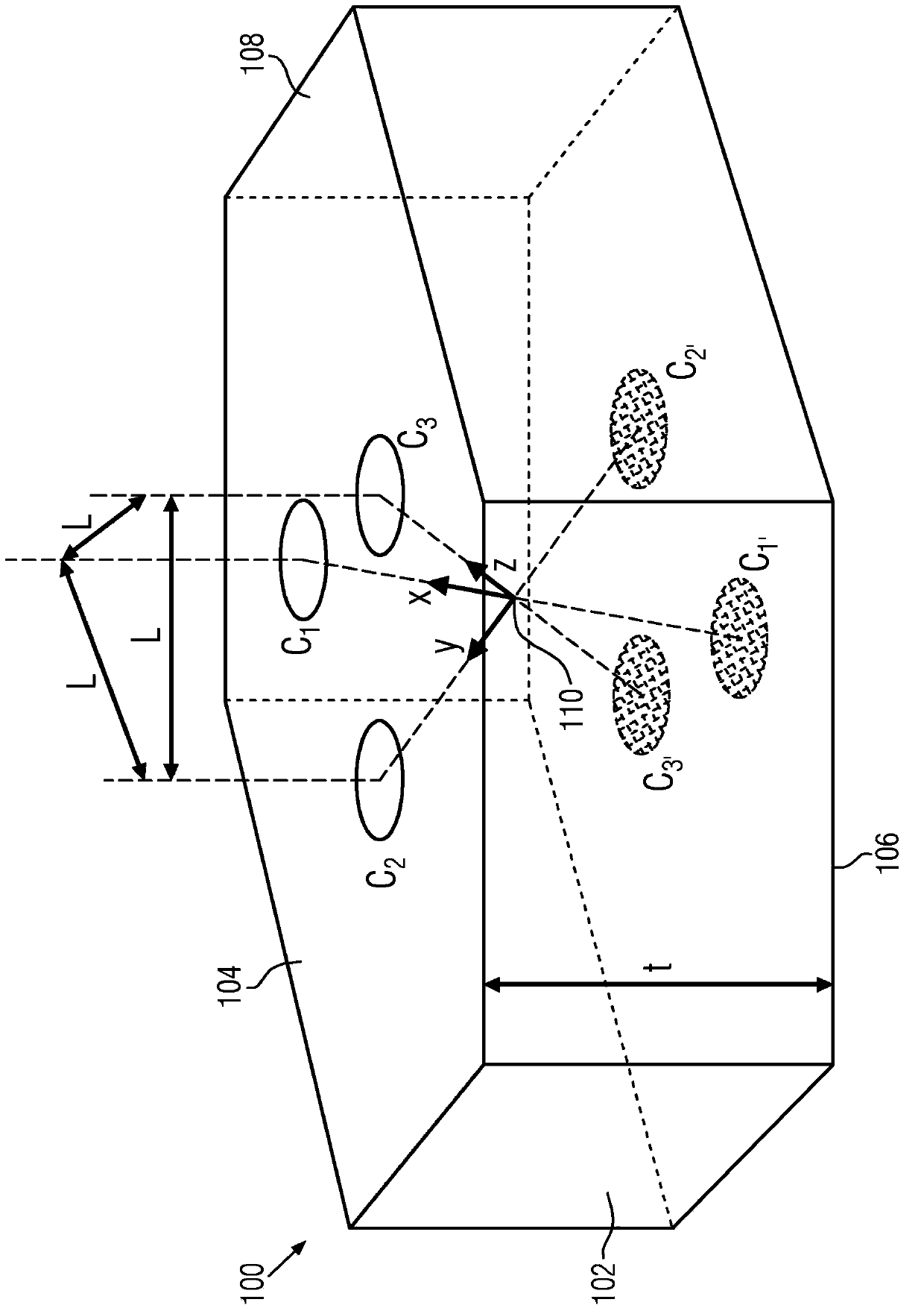
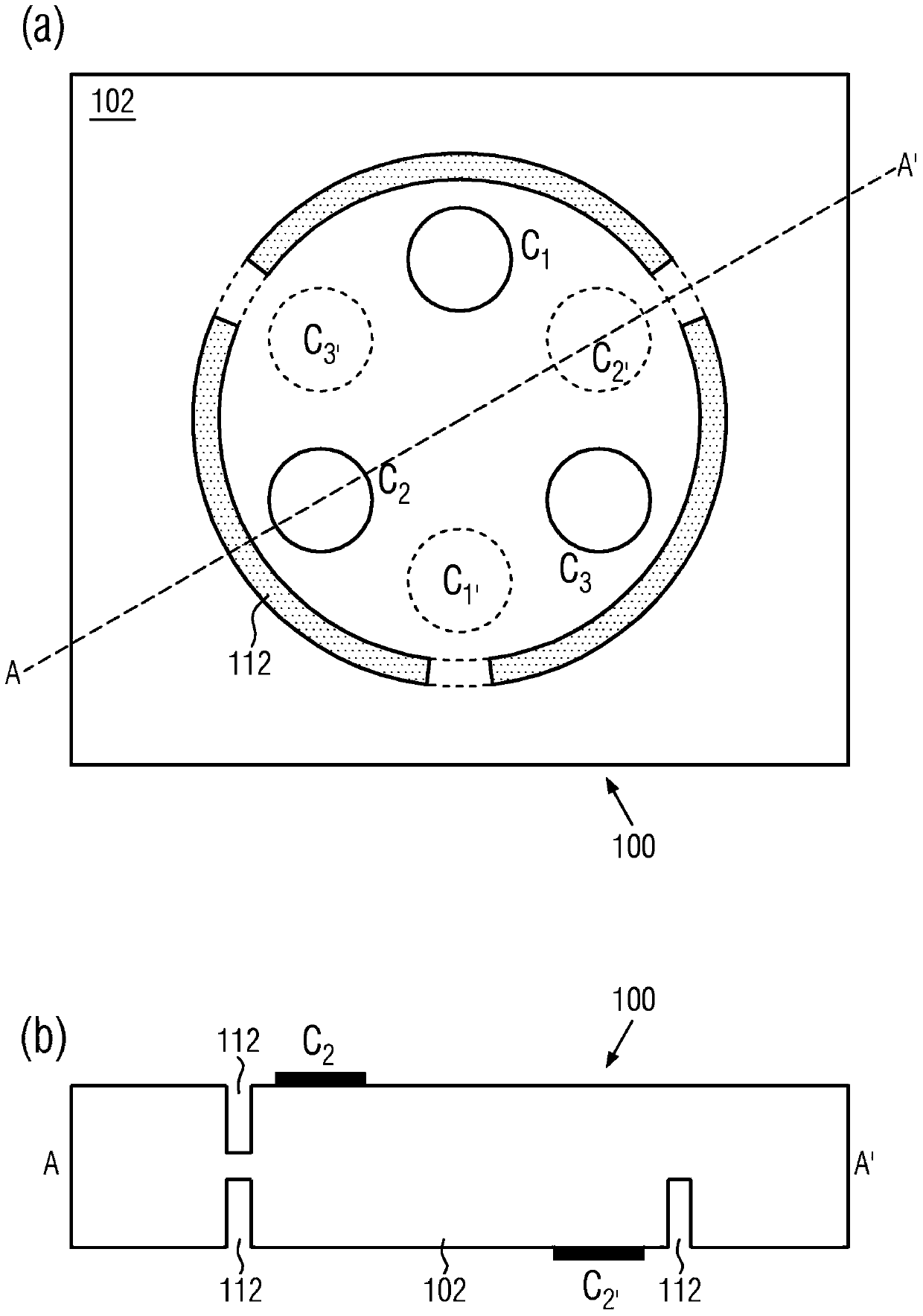
[0049] figure 1 The principle structure of the new magnetic field sensor in its most general design is shown. The magnetic field sensor 100 comprises a conductive substrate 102 which is delimited in the spatial direction by two ideally but not necessarily planar surfaces 104 , 106 , which are ideally but not necessarily oriented parallel to one another. The bounding surfaces 104 , 106 are subsequently referred to as upper or lower bounding surfaces. The conductive structure can be defined in two different spatial directions. At least three interfaces C i (i=1, 2...N, N≥3) and C i’ (i'=1, 2...N', N'≥3 and not necessarily equal to N) are integrated in the upper or lower interface 104, 106, respectively, via which the structure 100 can be electrically manipulated and the magnetic field-dependent Measure the signal.

[0050] During the operation of the magnetic field sensor 100, at the interface C of one of the bounding surfaces 104 i With the second interface C of the oppo...


PUM


Abstract

A three-dimensional Hall sensor can be used for detecting a spatial magnetic field. A method for measuring a spatial magnetic field can be performed using this Hall sensor. The Hall sensor comprises an electrically conducting base body and at least three electrode pairs, wherein each electrode pair has a first terminal and a second terminal, which are arranged such on the base body, that a current can flow from the first terminal to the second terminal through the base body. At least three first terminals are arranged on a first surface of the base body and at least three second terminals are arranged on the second surface, different from the first surface of the base body, wherein the first and the second surfaces oppose each other.

Description

technical field [0001] The invention relates to a three-dimensional Hall sensor for detecting spatial magnetic fields. Furthermore, the invention relates to a method for measuring a spatial magnetic field by means of the Hall sensor. Measure the three-dimensional magnetic field vector B, that is, its three components B about the coordinate system x, y, z x , B y , B z has great technical significance. Background technique [0002] Hall sensors are frequently used, for example, to measure movements in a contactless manner by means of a magnetic interaction between one or more permanent magnets and the Hall sensor. Such measurement of movement and position is used, for example, in pneumatics, in automation and robotics, and in the automotive sector for the control of machine tools. [0003] In particular, the contactless detection of movement offers the advantage of being wear-free. Among the known contactless measuring methods, optical and magnetic methods are the most ...

Claims


Application Information

Patent Timeline
IPC IPC(8): G01R33/07
CPCG01R33/072G01R33/07G01R33/0005G01R33/0206
Inventor 奥利弗·保罗帕特里克·鲁特阿夫塔卜·泰穆尔
Owner TDK MICRONAS 有限公司
Why Eureka
Try Eureka