Aircraft flutter prediction and analysis method and device

A predictive analysis and aircraft technology, applied in the direction of instruments, special data processing applications, electrical digital data processing, etc., can solve the problems of inaccuracy and low accuracy of flutter prediction and analysis, and achieve the effect of improving accuracy

Active Publication Date: 2014-12-03
BEIJING AERONAUTIC SCI & TECH RES INST OF COMAC +1
View PDF2 Cites 25 Cited by
  • Summary
  • Abstract
  • Description
  • Claims
  • Application Information

AI Technical Summary

Problems solved by technology

Therefore, the finite element model of the aircraft structure is obtained by using the finite element method, which is an approximate model of the aircraft structure, and when the finite element model is carried out on the aircraft structure, the obtained finite element model can only represent a small part of the The aircraft structure cannot fully represent the entire aircraft structure, so there is a certain inaccuracy, which leads to low accuracy of flutter prediction analysis

Method used


Image

  • Aircraft flutter prediction and analysis method and device
  • Aircraft flutter prediction and analysis method and device

Examples


Embodiment 1

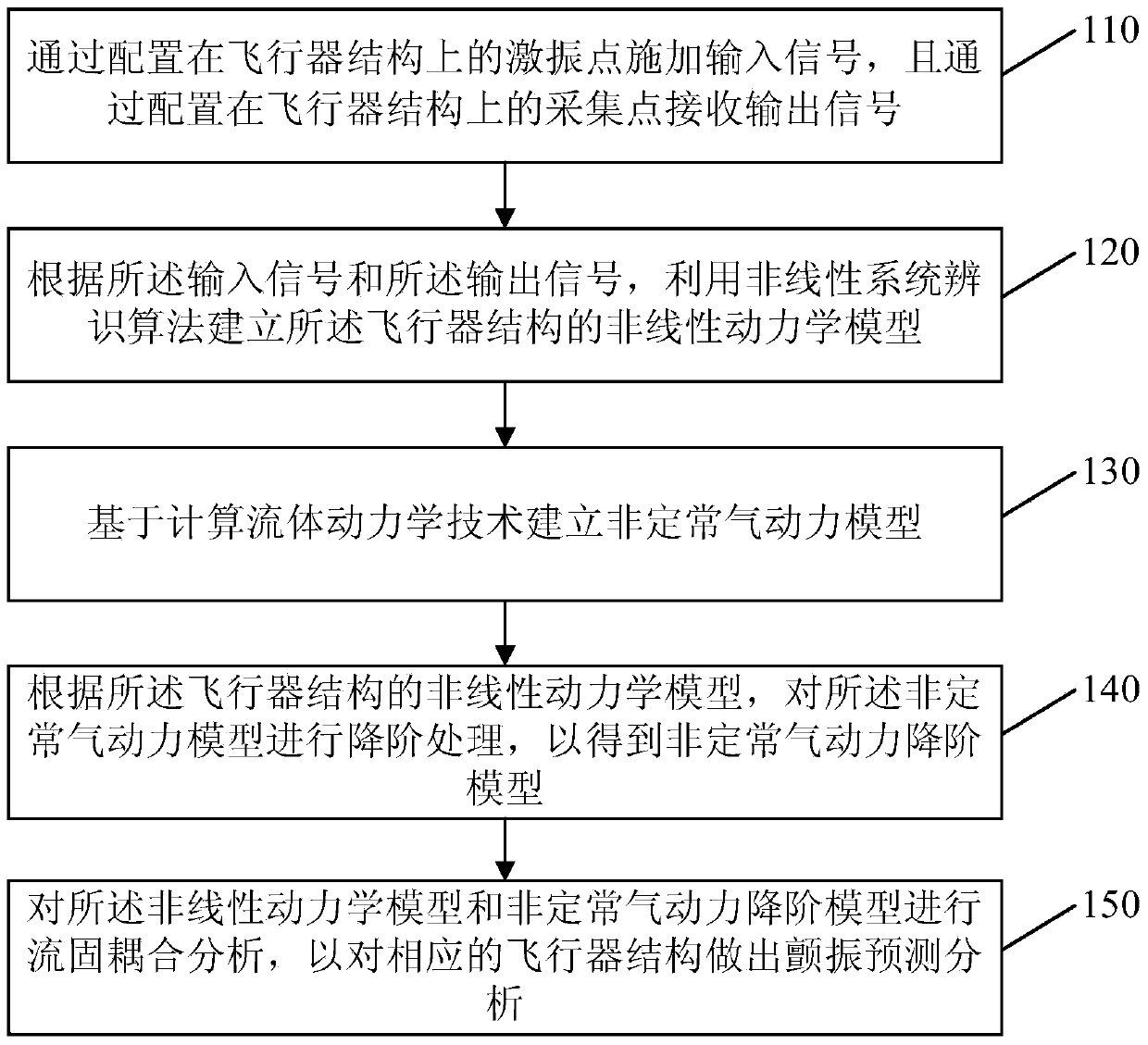
[0022] figure 1 It is a flow chart of the aircraft flutter prediction analysis method provided by Embodiment 1 of the present invention. This embodiment can be applied to perform flutter prediction analysis on a certain part of the aircraft structure (such as wings, empennages, etc.) or the overall structure. The method can be performed by The aircraft flutter prediction and analysis device can be implemented, and the device can be implemented by software and / or hardware, and cooperate with the excitation points and collection points configured on the aircraft structure to realize the analysis method. The method specifically includes the following steps:

[0023] Step 110, applying an input signal through an excitation point configured on the aircraft structure, and receiving an output signal through a collection point configured on the aircraft structure.

[0024] Wherein, the excitation point may be an excitation device configured on the aircraft structure for applying vibr...

Embodiment 2

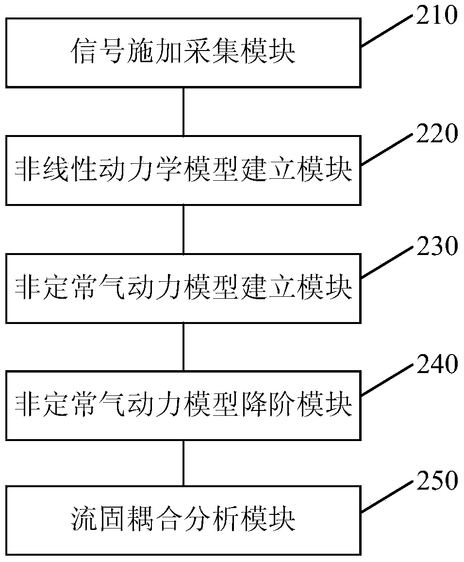
[0052] figure 2 It is a schematic diagram of an aircraft flutter prediction and analysis device provided in Embodiment 2 of the present invention. The aircraft flutter prediction and analysis device provided in Embodiment 2 of the present invention is used to implement the aircraft flutter prediction and analysis method provided in Embodiment 1. Such as figure 2 As shown, the aircraft flutter prediction and analysis device provided in Embodiment 2 includes a signal application acquisition module 210, a nonlinear dynamic model establishment module 220, an unsteady aerodynamic model establishment module 230, an unsteady aerodynamic model reduction module 240 and a flow Solid coupling analysis module 250 .

[0053] The signal applying and collecting module 210 is used for applying input signals through excitation points arranged on the aircraft structure, and receiving output signals through the collecting points arranged on the aircraft structure.

[0054] The nonlinear dyn...


PUM


Abstract

The invention discloses an aircraft flutter prediction and analysis method and device. The method comprises the following steps: applying an input signal through an exciting point on an aircraft structure, and receiving an output signal through a collection point which is configured on the aircraft structure; establishing a nonlinear kinetic model of the aircraft structure by utilizing a nonlinear system recognition algorithm according to the input signal and the output signal; establishing an unsteady aerodynamic model on the basis of the calculation fluid kinetic technology; performing reduced order for the unsteady aerodynamic model according to the nonlinear kinetic model of the aircraft structure to obtain a reduced order model; performing the fluid-structure interaction analysis on the nonlinear kinetic model and the reduced order model so as to make the flutter prediction and analysis on the corresponding aircraft structure. Since the nonlinear kinetic model of the aircraft structure is acquired by performing the test according to the real aircraft structure, the accuracy in flutter prediction and analysis can be improved.

Description

technical field [0001] Embodiments of the present invention relate to an aircraft structural performance analysis technology, and in particular to an aircraft flutter prediction analysis method and device. Background technique [0002] Flutter is an aeroelastic instability phenomenon caused by the interaction between structural deformation and aerodynamic force. It is a self-excited vibration of an elastic structure with no attenuation in amplitude under the coupling action of aerodynamic force, elastic force and inertial force. The occurrence of flutter can lead to structural damage and lead to serious accidents. Therefore, it is very important to perform flutter analysis on the aircraft, and the flutter analysis of the aircraft runs through the entire process of aircraft design. Flutter research includes theoretical flutter research, wind tunnel flutter test, ground flutter test, and aircraft flutter flight test. In the pre-conceptual design and preliminary design of the...

Claims


Application Information

Patent Timeline
Patent Type & Authority Applications(China)
IPC IPC(8): G06F17/50
Inventor 曾杰
Owner BEIJING AERONAUTIC SCI & TECH RES INST OF COMAC
Why Eureka
Try Eureka