Movable autobus card swiping machine
A bus card swiping machine, mobile technology, applied in the field of card swiping machines, can solve problems such as efficient manual charging, unfavorable bus charging, passenger fare evasion, etc., to improve the efficiency of swiping cards, facilitate swiping operations, and avoid serious damage.
- Summary
- Abstract
- Description
- Claims
- Application Information
AI Technical Summary
Problems solved by technology
Method used
Image
Examples
Embodiment 1
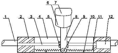
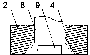
[0021] like figure 1 and figure 2 As shown, this embodiment includes a support rod 1 and a mounting base 2 fixed on the support rod 1, a motor 12 is arranged in the mounting base 2, a screw rod 3 is connected to the output end of the motor 12, and a The dovetail groove 4 also includes a column 8, the column 8 is fixed with a screw nut 5, the screw nut 5 cooperates with the screw mandrel 3, the top of the column 8 is fixed with a card reader, and the bottom end of the column 8 is provided with a matching slot for the dovetail groove 4. Protrusion, and roller 9 is installed on the protrusion, and two springs 11 are also installed in dovetail groove 4, and the two ends of two springs 11 are connected with the groove wall of dovetail groove 4 and the side outer wall of column 8 respectively. During the work of the present invention, the support bar 1 is horizontally arranged at the charging position of the front door of the bus, and can extend to the middle part of the car body ...
Embodiment 2
[0023] like figure 1 As shown, on the basis of Embodiment 1, the present embodiment includes a plurality of reader-writers 6 and a display screen 7 connected to the reader-writers 6, and the plurality of reader-writers 6 are distributed in a circular array. The top of column 8. When swiping the card by car, especially during the crowded period, the existing single reader 6 is often blocked by passengers, which causes other passengers to be unable to swipe the card or it is inconvenient to swipe the card. The card reader at the top of the column 8 is a plurality of readers 6 The formed ring structure makes it possible to swipe the card within 360 °, which is convenient for passengers to swipe the card. The display screen 7 electrically connected to the reader 6 can display the information in the bus card of the passenger to remind the passenger to recharge and pay.
Embodiment 3
[0025] like figure 1 As shown, on the basis of Embodiment 1, this embodiment also includes two travel switches 10 electrically connected to the motor 12, the two travel switches are placed at the bottom of the dovetail groove 4, and the spring 11 is placed Compressed to the position of maximum deformation. The movement of the column 8 is realized by the cooperation of the screw rod 3 and the screw nut 5. When the column 8 moves freely in the horizontal direction, two springs 11 located between the outer wall of the column 8 and the end of the dovetail groove 4, one spring 11 is compressed , the other spring 11 is stretched, when the compression or stretching deformation of the spring 11 exceeds its own maximum deformation, the spring 11 will be damaged or directly scrapped; when the spring 11 is compressed or stretched Travel switches are respectively installed at the positions to the maximum deformation amount. When the column 8 moves to contact with the travel switch, the t...
PUM
 Abstract
Description
Claims
Application Information
 - R&D
- Intellectual Property
- Life Sciences
- Materials
- Tech Scout
- Unparalleled Data Quality
- Higher Quality Content
- 60% Fewer Hallucinations
Browse by: Latest US Patents, China's latest patents, Technical Efficacy Thesaurus, Application Domain, Technology Topic, Popular Technical Reports.
© 2025 PatSnap. All rights reserved.Legal|Privacy policy|Modern Slavery Act Transparency Statement|Sitemap|About US| Contact US: help@patsnap.com


