Linear and rotary motion converter for V-type magnetic pole

A technology of rotary motion and converter, which is applied in the field of V-shaped magnetic pole linear rotary motion converter, can solve the problems of reducing the service life of the converter, damaging the shaft and equipment, etc., and achieves the goal of optimizing waveform, avoiding noise and vibration, and improving utilization rate Effect

Inactive Publication Date: 2014-12-03
SOUTHEAST UNIV
View PDF6 Cites 2 Cited by
  • Summary
  • Abstract
  • Description
  • Claims
  • Application Information

AI Technical Summary

Problems solved by technology

[0004] The method of tilting the permanent magnet can eliminate the torque ripple of the conversion structure, but the one-way tilt of the permanent magnet will cause axial magnetic pulling force, and the unbalanced axial force may damage the shaft and equipment, reducing the service life of the converter

Method used


Image

  • Linear and rotary motion converter for V-type magnetic pole
  • Linear and rotary motion converter for V-type magnetic pole
  • Linear and rotary motion converter for V-type magnetic pole

Examples


Embodiment 1

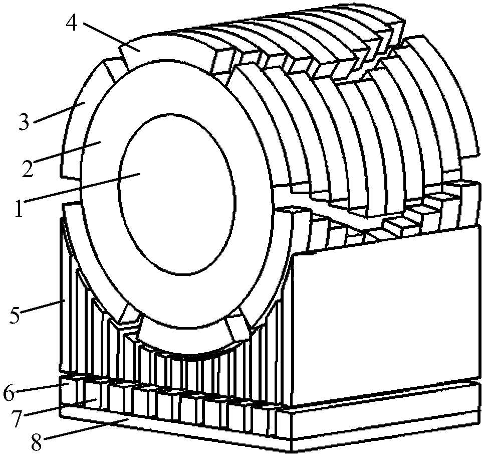
[0020] Embodiment 1: as figure 1 The shown V-shaped magnetic pole linear rotary motion converter includes a rotary unit, a linear unit and a magnetic modulation mechanism, and the magnetic modulation mechanism is fixedly arranged between the rotary unit and the linear unit.

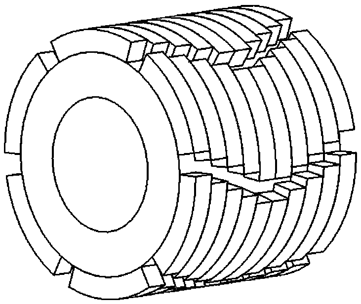
[0021] Such as figure 2 As shown, the rotating unit includes a rotating shaft 1, a rotor core 2 and permanent magnets. The rotating shaft 1 passes through the shaft hole of the rotor core 2 and is fastened together with the rotor core 2 , and the permanent magnet is pasted on the surface of the rotor core 2 . Wherein, the permanent magnets include a rotor N-pole permanent magnet 3 and a rotor S-pole permanent magnet 4, and the rotor N-pole permanent magnet 3 and the rotor S-pole permanent magnet 4 are radially magnetized tile-shaped permanent magnets. The permanent magnets of each pole of the rotating unit are arranged along the circumference of the rotor core 2 to form a multi-stage annular permanent ...

Embodiment 2

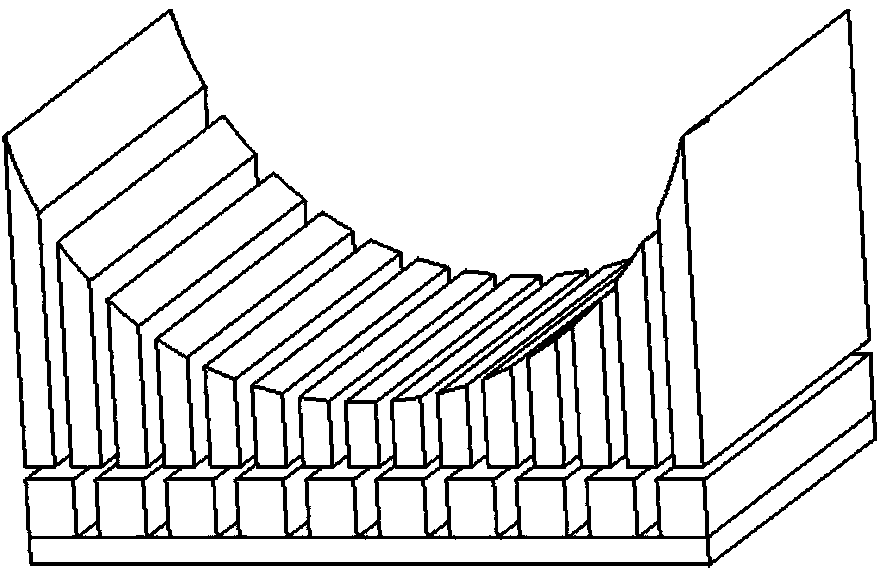
[0023] Embodiment 2: The only difference from Embodiment 1 is that the permanent magnet in the rotating unit is embedded in the rotor core 2 . The linear unit includes a mover yoke 8 and a mover N-pole permanent magnet 6 magnetized in the radial direction; the mover N-pole permanent magnet 6 is pasted on the surface of the mover yoke 8 along the moving direction of the linear unit. The N pole permanent magnet 6 of the mover and the S pole permanent magnet 7 of the mover in the linear unit are interlaced and embedded in the mover yoke 8 along the moving direction of the linear unit. In addition, the mover N-pole permanent magnet 6 in the mover yoke 8 can also be embedded in the mover yoke 8 along the moving direction of the linear unit.

[0024] In addition, the mover N pole permanent magnet 6 in the mover yoke 8 can also be replaced by the mover S pole permanent magnet 7 .

[0025] In this linear rotary motion converter, the magnetic lines of force generated by the permanent ...


PUM


Abstract

The invention discloses a linear and rotary motion converter for a V-type magnetic pole. According to the linear and rotary motion converter, linear motion and rotary motion can be mutually converted, and kinetic energy transfer can be achieved. The converter comprises a rotary unit, a linear unit and a magnetism adjusting mechanism. The rotary unit comprises a rotating shaft, a rotor core and a permanent magnet, wherein the permanent magnet is of a segmented V-type structure and is pasted on the surface of the rotor core. The linear unit comprises a mover yoke and a permanent magnet. The magnetism adjusting mechanism is composed of permeable magnetism adjusting iron blocks and fixed between the rotary unit and the linear unit. As the rotary unit is of a novel magnetic pole structure, the torque pulsation of the converter is effectively reduced, jitter and loss of the converter are reduced, and the stability and energy conversion efficiency of the converter are improved. Meanwhile, the V-type magnetic pole is centrosymmetric, so that axial magnetic pulls are mutually offset, the operational reliability of the converter is improved, and the service life of the converter is prolonged.

Description

technical field [0001] The invention relates to a V-shaped magnetic pole linear rotary motion converter, which is suitable for non-contact variable speed driving occasions and belongs to the technical field of power transmission. Background technique [0002] In the fields of industrial and agricultural production, national defense, aviation, aerospace and other fields, it is often necessary to change rotary motion into linear motion, or convert linear motion into rotary motion. According to different applications, people have developed various conversion devices or equipment to meet the above requirements, such as rack and pinion, chain, wire rope, transmission belt, screw rod, crank connecting rod, slider mechanism, cam ejector mechanism, etc. In these transforming devices, linear motion parts and rotary motion parts are in contact with each other, causing problems of friction, vibration, noise, and the like. [0003] Permanent magnet rack and pinion is a non-contact tran...

Claims


Application Information

Patent Timeline
Patent Type & Authority Applications(China)
IPC IPC(8): H02K51/00
Inventor 付兴贺王标林明耀
Owner SOUTHEAST UNIV
Why Eureka
Try Eureka