Method and device for sealing end faces of film bundle

A sealing device and end face technology, applied in suction devices, dialysis systems, etc., can solve the problems of long production time, high maintenance cost of laser parts, and high production and manufacturing costs, and achieve lower production costs, complete membrane sealing effect, and reduce The effect of the production process

Active Publication Date: 2014-12-10
SUZHOU JUN KANG MEDICAL TECH
View PDF5 Cites 6 Cited by
  • Summary
  • Abstract
  • Description
  • Claims
  • Application Information

AI Technical Summary

Problems solved by technology

[0004] Laser sintering method: it uses laser light to directly irradiate the end face of the membrane bundle, and sinters the membrane filaments on the laser path through its high temperature melting. This method is affected by the laser energy, and the penetration is limited, so it cannot guarantee the complete sealing of the end face of the membrane bundle. The energy consumption of sintering is high, and the maintenance cost of laser components is also high;
[0005] Electrothermal infrared sintering method: it uses the infrared thermal effect generated by the hot plate to sinter the end face of the film bundle. During the sintering process, the hot plate is kept out of contact with the product to prevent the film filament from sticking to the hot plate after melting. However, the hot plate cannot contact the film bundle. The contact is offset, so the sintered surface is not smooth, and the complete sealing of the end surface of the membrane bundle cannot be guaranteed;
[0006] Two-time glue injection method: After putting the film bundle into the main shell, use a fully sealed rubber cover to seal both ends of the main shell. When the first glue is injected, the amount of

Method used


Image

  • Method and device for sealing end faces of film bundle
  • Method and device for sealing end faces of film bundle
  • Method and device for sealing end faces of film bundle

Examples


Embodiment Construction

[0030] The present invention will be further described in detail below in conjunction with the accompanying drawings, so that those skilled in the art can implement it with reference to the description.

[0031] The invention provides a membrane bundle end face sealing method, comprising the following steps:

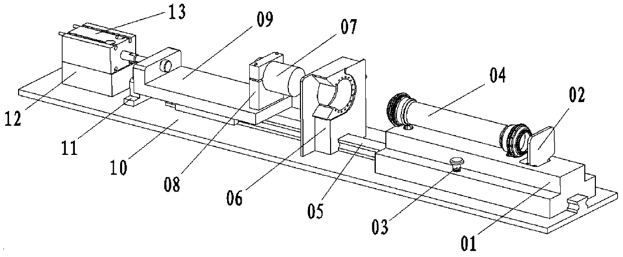
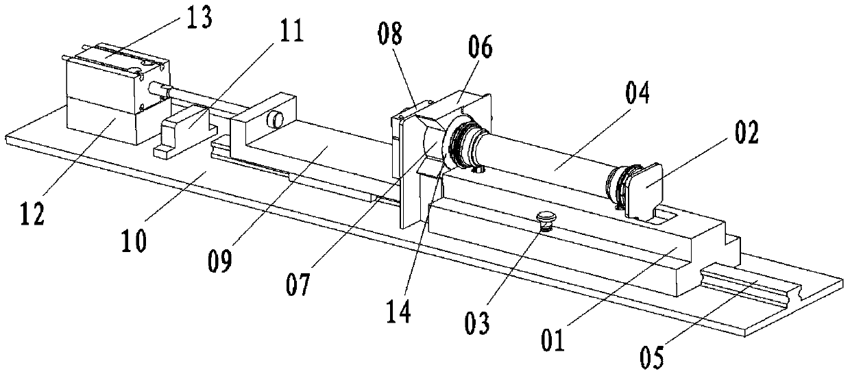
[0032] Step 1. Buckle the rubber injection cover 043 on the two ends of the main housing 041 of the hemodialyzer respectively, and then put the hollow fiber membrane bundle 044 into the main housing 041 on which the rubber injection cover 043 has been installed, and make it The length of the end face of the hollow fiber membrane bundle 044 extending beyond the end face of the concentric ring column 0431 of the injection cover is 0.5-2 mm, and the material of the membrane bundle 044 is polyethersulfone (PES) or polysulfone (PSU), The material of the injection cover 043 is selected from polypropylene (PP) or polyethylene (PE), and thus the processed part 04 of the hemodial...


PUM

PropertyMeasurementUnit
Lengthaaaaaaaaaa
Thicknessaaaaaaaaaa
Thicknessaaaaaaaaaa

Abstract

The invention discloses a method and device for sealing the end faces of a film bundle. The device for sealing the end faces of the film bundle comprises a base plate, a working part arranged on the base plate, a base and a hot plate, wherein the base and the hot plate are located on the two sides of the working part respectively. A through hole is formed in a working plate of the working part, a plurality of suction holes are formed in the edge of the circumference of the through hole and connected with an air pipe, two positioning holes are formed in the top of the base, a rail groove is formed in the bottom of the base and matched with a guide rail of the base plate, the hot plate is fixed through a hot plate base, and a driving mechanism is connected to the hot plate base. The method for sealing the end faces of the film bundle includes the step that the end faces of the hollow fiber film bundle are sealed in the mode that aluminum foil sheets are arranged on the end faces of a glue injecting cover in a hot-seal mode. Secondary glue injecting is avoided, production working procedures are reduced, the production and manufacturing cost is effectively reduced, and the complete film silk sealing effect can be played.

Description

technical field [0001] The invention relates to a membrane bundle end face sealing method and a sealing device, belonging to the technical field of hemodialyzer manufacture. Background technique [0002] The hemodialyzer mainly uses the principle of semi-permeable membrane to introduce the patient's blood and dialysate into the hemodialyzer at the same time. The two flow in opposite directions on both sides of the dialysis membrane. Pressure gradient to achieve the purpose of removing toxins and excessive water retention in the body, replenishing the substances needed in the body, and maintaining electrolyte and acid-base balance. [0003] During the manufacturing process of the hemodialyzer, it is necessary to bundle the hollow fiber membranes into bundles, cut them flat and put them into the main casing, and then sinter the end faces of the membrane bundles to realize the sealing of the blood channel on the end faces of the membrane bundles. In the prior art, laser sinter...

Claims


Application Information

Patent Timeline
IPC IPC(8): A61M1/16
CPCA61M1/1621
Inventor 黄臣勇张婷婷邢雪奎高庆丰
Owner SUZHOU JUN KANG MEDICAL TECH
Why Eureka
Try Eureka