Supercharge Your Innovation With Domain-Expert AI Agents!

Injection needle switch valve

A switch valve and glue injection technology, which is applied in the direction of coating and surface coating liquid device, etc., can solve the problems of lower working efficiency, glue dripping, lack of glue needle control, etc., so as to avoid glue dripping and realize precision The effect of control

Inactive Publication Date: 2016-08-24
肖根福罗格注胶技术(苏州工业园区)有限公司
View PDF4 Cites 0 Cited by
  • Summary
  • Abstract
  • Description
  • Claims
  • Application Information

AI Technical Summary

Problems solved by technology

[0002] The injection needle structure of the currently used glue injection equipment is as follows: figure 1 As shown, , and the dispensing needle 3 are installed on the dispensing head mounting plate 1 through the dispensing needle seat 2, and there is no switch valve set between the three, and the control of the dispensing needle 3 is lacking during the dispensing process. Therefore, this traditional glue injection has the following two main problems. 1. After the glue preparation system stops pressing glue, because there will be residue in the glue outlet needle 3, the glue will not stop immediately at the needle, and glue dripping will occur. , thus affecting the quality of glue injection and reducing work efficiency

Method used


Image

  • Injection needle switch valve
  • Injection needle switch valve
  • Injection needle switch valve

Examples


Embodiment Construction

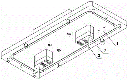
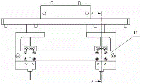
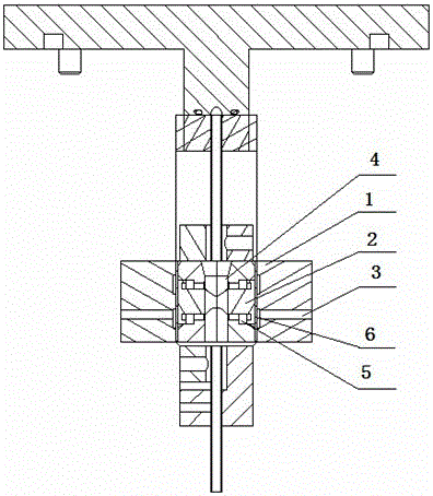
[0014] The invention discloses a glue injection needle switch valve, which is used to control the glue out of the glue injection needle. figure 2 , image 3 As shown, the injection needle on-off valve 11 is arranged on the injection needle seat, including the valve shell, the closing system inside the valve and the reset system.

[0015] The valve shell 1 is provided with a vent hole 3, and the closed system includes a flexible tube 4 for being sleeved on the injection needle tube, a movable valve core 2 placed on both sides of the flexible tube 4, and a valve core set on the valve. Diaphragm 6 on the outside of core 2. The flexible tube 4 is a silicone tube, and the valve core diaphragm 6 is perpendicular to the vent hole 3. When the vent hole 3 is ventilated, the valve core diaphragm 6 is pushed, thereby driving the valve core 2 to the flexible tube 4. Squeeze the flexible tube at all times.

[0016] The reset system is composed of an elastic element 5 arranged inside th...


PUM


Abstract

The invention discloses a glue injection needle switch valve, which includes a valve casing, a closing system and a reset system located in the valve casing; the valve casing is provided with a vent hole, and the closure system includes a The flexible tube on the top, the movable valve core placed on both sides of the flexible tube, and the valve core diaphragm arranged outside the valve core. The valve core diaphragm is perpendicular to the vent hole and ventilates the vent hole to drive The diaphragm of the valve core pushes the valve core to squeeze the flexible tube. The reset system is composed of an elastic element for reset inside the valve core. . This device can effectively realize the precise control of the injection needle during the injection process, avoiding the glue injection that could not be stopped immediately in the past production process and the glue dripping phenomenon that is easy to occur in the vacuum operation, and improves the quality of the injection at the same time It also greatly improves the production efficiency of the enterprise.

Description

technical field [0001] The invention relates to a glue injection needle switch valve, in particular to a glue injection needle switch valve suitable for a glue injection device, and belongs to the field of mechanical equipment. Background technique [0002] The injection needle structure of the currently used glue injection equipment is as follows: figure 1 As shown, , and the dispensing needle 3 are installed on the dispensing head mounting plate 1 through the dispensing needle seat 2, and there is no switch valve set between the three, and the control of the dispensing needle 3 is lacking during the dispensing process. Therefore, this traditional glue injection has the following two main problems. 1. After the glue preparation system stops pressing glue, because there will be residue in the glue outlet needle 3, the glue will not stop immediately at the needle, and glue dripping will occur. , thus affecting the quality of glue injection and reducing work efficiency. Con...

Claims


Application Information

Patent Timeline
Patent Type & Authority Patents(China)
IPC IPC(8): B05C5/02B05C11/10
Inventor 唐修全
Owner 肖根福罗格注胶技术(苏州工业园区)有限公司
Features
  • R&D
  • Intellectual Property
  • Life Sciences
  • Materials
  • Tech Scout
  • Unparalleled Data Quality
  • Higher Quality Content
  • 60% Fewer Hallucinations
Learn More