Shaft sleeve shaper and working method thereof

A shaping machine and shaft sleeve technology, applied in the direction of manufacturing tools, metal processing equipment, feeding devices, etc., can solve the problems of inconvenient use, and achieve the effects of easy collection of finished products, improved production efficiency, and stable working process

Inactive Publication Date: 2014-12-10
嘉善新易能精密机械设备厂
View PDF9 Cites 3 Cited by
  • Summary
  • Abstract
  • Description
  • Claims
  • Application Information

AI Technical Summary

Problems solved by technology

[0003] At present, most of the existing shaft sleeve shaping machines are manually loaded, that is, the operator sends the material into the shaping fram

Method used


Image

  • Shaft sleeve shaper and working method thereof
  • Shaft sleeve shaper and working method thereof
  • Shaft sleeve shaper and working method thereof

Examples


Embodiment Construction

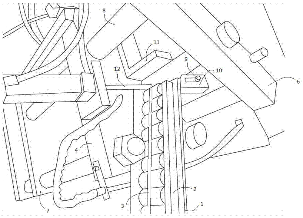
[0032] The specific implementation of above-mentioned shaft sleeve shaping machine is as follows:

[0033] Such as figure 1 As shown, the feeding mechanism is composed of a feeding plate 1, a fixing bar 2, and a fixing rod 3; The lower positioning plate 10, the front positioning plate 11, the limit pin 12, and the second column 9 are formed.

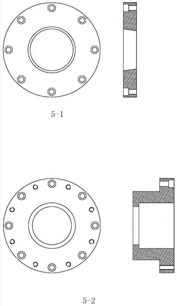
[0034] Such as image 3 As shown, the formwork mounting structure is installed by pressing plate 5-1 and inserting 5-2 cover openings.

[0035] The two ends of the feed plate 1 are fixedly connected with the fixed strip 2; the top of the fixed strip on one side is connected to the telescopic bracket, and the other end of the telescopic bracket is connected to the fixed rod 3, and the direction of the fixed rod 3 is parallel to the feed plate 1, and is located between the two fixed strips 2 between.

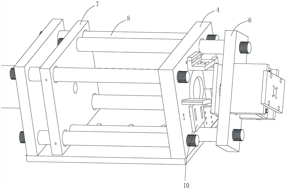
[0036] The middle part of the base 4 is open, and the surface is provided with through holes, and its left and right sides are respec...


PUM


Abstract

The invention discloses a working method of a shaft sleeve shaper. The shaft sleeve shaper consists of a feeding mechanism, a shaping mechanism, a connecting mechanism and a motor, wherein the shaping mechanism comprises a base, a baseplate, a mold frame mounting structure, a left slide plate and a right slide plate; the middle of the base is opened; a through hole is formed in the surface of the base; the left slide plate and the right slide plate are respectively arranged at the left and right sides of the base; the left slide plate and the right slide plate are connected through a first stand column penetrating through the through hole in the surface of the base; the motor provides the traction force to the right slide plate; a shaping ejector pin is mounted in the middle of the right slide plate; a stripping ejector pin is mounted in the middle of the left slide plate; the connecting mechanism comprises a lower positioning plate, a front positioning plate and a limiting needle; the side surface of the front positioning plate is L-shaped; the vertical part of the front positioning plate is fixedly connected to the base; the projection part of the front positioning plate is connected to the top of the through ole of a pressure plate; the lower positioning plate is driven by a cylinder, and is connected with the base through a second stand column; a bracket is arranged on the inclined surface of the lower positioning plate; the middle of the bracket is inclined; and the bottom and top of the bracket horizontally extend to one side.

Description

technical field [0001] The invention relates to the field of metal shaft sleeve shaping, in particular to a shaft sleeve shaping machine and a working method thereof. Background technique [0002] The shaft sleeve part is one of the typical parts often encountered in the machine. It is mainly used to support transmission parts, transmit torque and bear load. The shaft sleeve part is a rotating body part, its length is greater than its diameter, and generally consists of an outer cylindrical surface, a conical surface, an inner hole, a thread and a corresponding end surface of a concentric shaft. According to different structural shapes, bushing parts can be divided into optical shafts, stepped shafts, hollow shafts and crankshafts. A shaft with an aspect ratio of less than 5 is called a short shaft, and one with an aspect ratio greater than 20 is called a slender shaft, and most shafts are in between. The shaft is supported by bearings, and the shaft section that fits wit...

Claims


Application Information

Patent Timeline
IPC IPC(8): B21D3/00B21D43/02B21D43/20B21D45/06
Inventor 吴永浩
Owner 嘉善新易能精密机械设备厂
Why Eureka
Try Eureka