
Automatic-moving-type electric vehicle power supply system and power supply method thereof

A mobile power supply and power supply system technology, applied in electric vehicles, signal transmission systems, battery circuit devices, etc., can solve the problems of long waiting time and inability to drive electric vehicles, so as to reduce waiting time, improve networking, and reduce atmospheric pressure. The effect of pollution

Active Publication Date: 2014-12-10
CHINA UNIV OF MINING & TECH (BEIJING)
View PDF4 Cites 52 Cited by
  • Summary
  • Abstract
  • Description
  • Claims
  • Application Information

AI Technical Summary

Problems solved by technology

[0008] The purpose of the present invention is to provide an autonomous mobile electric vehicle power supply system, the electric vehicle power supply system includes a rail-type mobile power supply vehicle that can move autonomously, and the electric vehicle can automatically obtain power supply services after entering the autonomous mobile electric vehicle power supply system , and the electric vehicle can be charged at the same time in the process of driving, which greatly reduces the waiting time for the charging operation, and is used to solve the problem that the existing charging pile of the electric vehicle has a fixed charging location. The problem

Method used


Image

  • Automatic-moving-type electric vehicle power supply system and power supply method thereof
  • Automatic-moving-type electric vehicle power supply system and power supply method thereof
  • Automatic-moving-type electric vehicle power supply system and power supply method thereof

Examples


Embodiment Construction

[0042] The invention will be described in further detail below in conjunction with the accompanying drawings.

[0043] Embodiment of the autonomous mobile electric vehicle power supply system of the present invention:

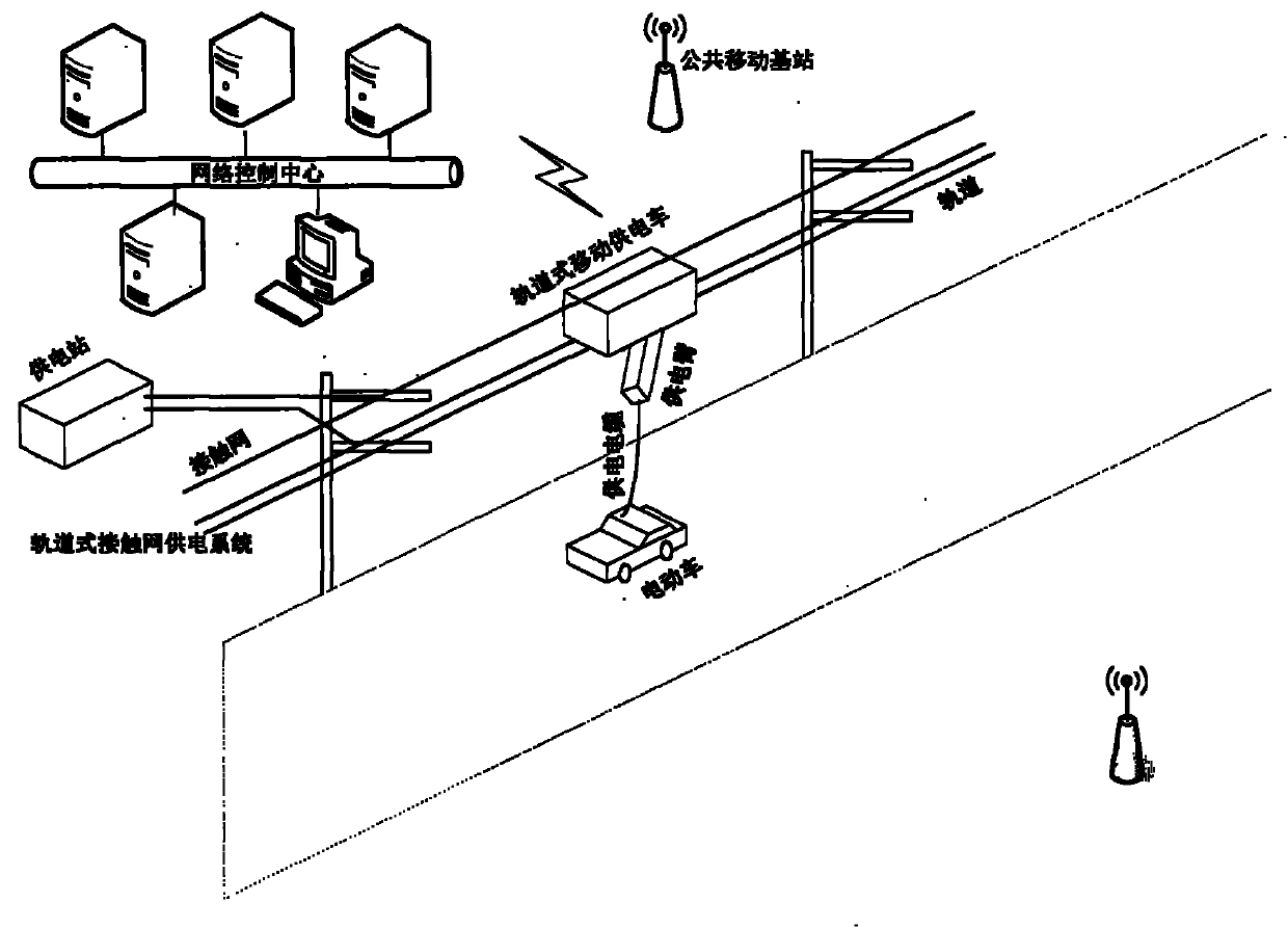
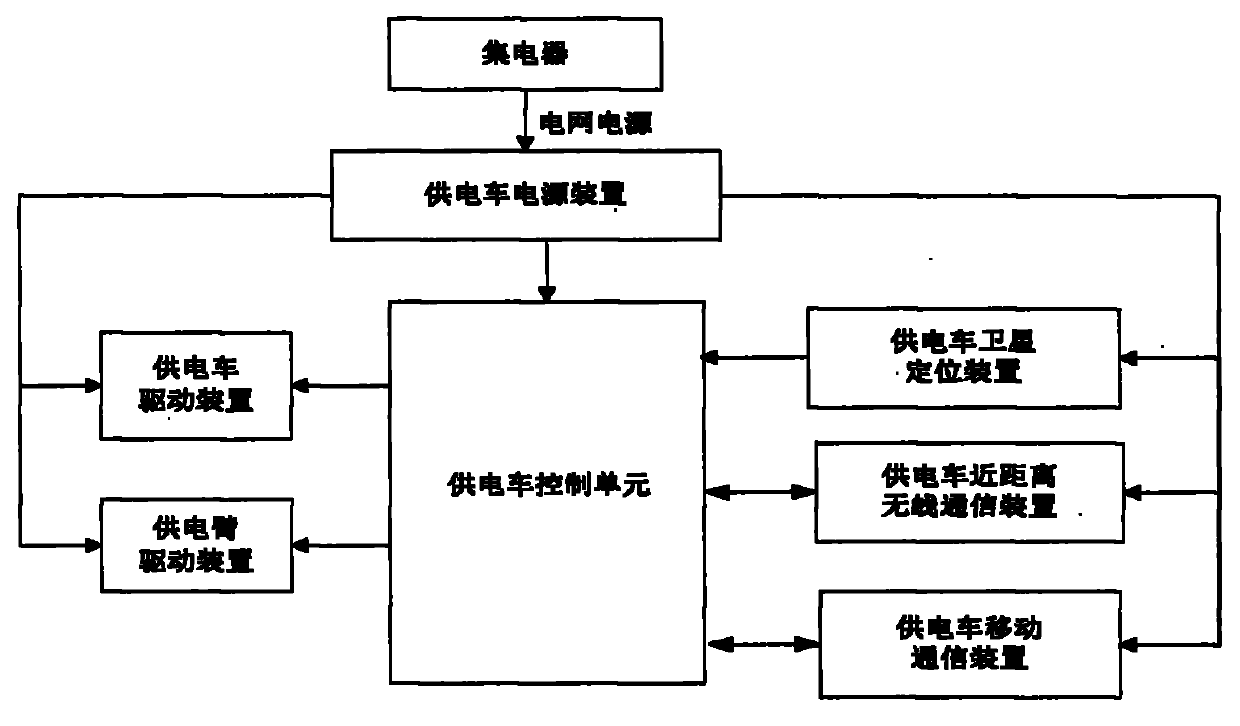
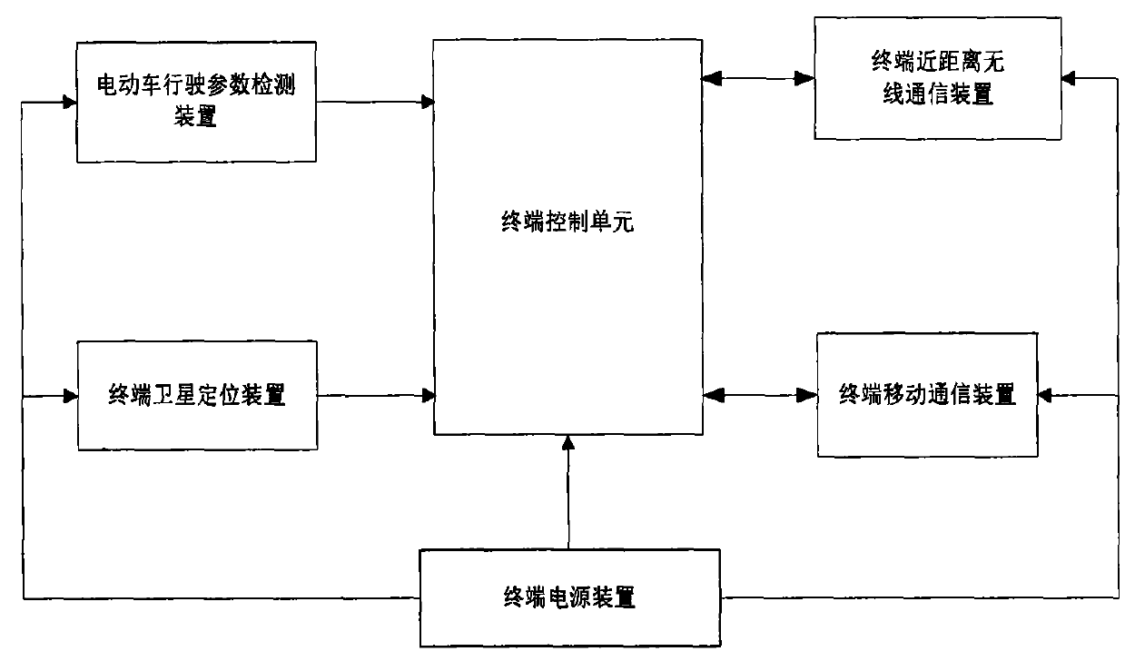
[0044] Such as figure 1 As shown, the power supply system of the present invention includes a network control center, a rail-type catenary power supply system, a rail-type mobile power supply vehicle and a power supply control terminal. The power supply control terminal is installed on the electric vehicle. The track type catenary power supply system is composed of power supply station, catenary and track, and the network control center is composed of server and mobile communication system.

[0045] The network control center communicates with the power supply control terminal and the rail-type mobile power supply vehicle through the mobile communication system. The power supply control terminal sends a power supply request to the network control center, and t...


PUM


Abstract

The invention relates to an automatic-moving-type electric vehicle power supply system and a power supply method thereof. The power supply system comprises a network control center, a rail-type contact network power supply system, a rail-type moving power supply vehicle and a power supply control terminal. A power grid power supply is introduced through the rail-type contact network power supply system, and accordingly the rail-type moving power supply vehicle is driven to move along a rail automatically. The power supply control terminal on an electric vehicle applies for power supply service to the network control center, the network control center controls the rail-type moving power supply vehicle to move to the position where the electric vehicle is located, and the rail-type moving power supply vehicle monitors running parameters of the electric vehicle through the power supply control terminal and charges the electric vehicle in the running process of the electric vehicle. The system can meet power supply requirements of the electric vehicle running for a long distance, and the electric vehicle does not need to stop for charging and can be charged during running. The problems that charging places of charging piles of existing electric vehicles are fixed, the electric vehicles cannot move during charging and waiting time is long are solved.

Description

technical field [0001] The invention relates to an autonomous mobile electric vehicle power supply system, which includes catenary power supply technology, electric drive technology, satellite positioning technology, wireless communication technology and network control technology, and is especially suitable for long-distance mobile power supply for electric vehicles. Including autonomous mobile electric vehicle power supply system and autonomous mobile power supply method. Background technique [0002] The trolley bus has a large number of operations in some urban public transportation, and the electric power of the trolley bus is obtained through a pair of overhead cables and a power collecting pole on the roof. The catenary of the trolleybus power supply system is only used for closed public transportation, not for social public trams. With the advancement of technology, electric vehicles used by the public in society have begun to be used more and more, but special fixe...

Claims


Application Information

Patent Timeline
IPC IPC(8): B60L11/18H02J7/00G08C17/02
CPCY02T10/70
Inventor 孙继平郭建昌
Owner CHINA UNIV OF MINING & TECH (BEIJING)
Learn More