Electrically controlled pneumatic braking system of vehicle

A technology of pneumatic braking and service braking, which is applied in the direction of brakes, vehicle parts, braking transmission devices, etc., can solve the problems of inconvenient switching between manual driving and unmanned driving, and achieve the avoidance of unilateral misoperation, low cost, Apply a wide range of effects

Active Publication Date: 2014-12-10
BEIJING INSTITUTE OF TECHNOLOGYGY
View PDF6 Cites 50 Cited by
  • Summary
  • Abstract
  • Description
  • Claims
  • Application Information

AI Technical Summary

Problems solved by technology

For commercial vehicles using pneumatic braking, the existing electronically controlled pneumatic auxiliary braking device is not develop

Method used


Image

  • Electrically controlled pneumatic braking system of vehicle
  • Electrically controlled pneumatic braking system of vehicle

Examples


Embodiment Construction

[0030] The present invention will be described in detail below in conjunction with the accompanying drawings and embodiments.

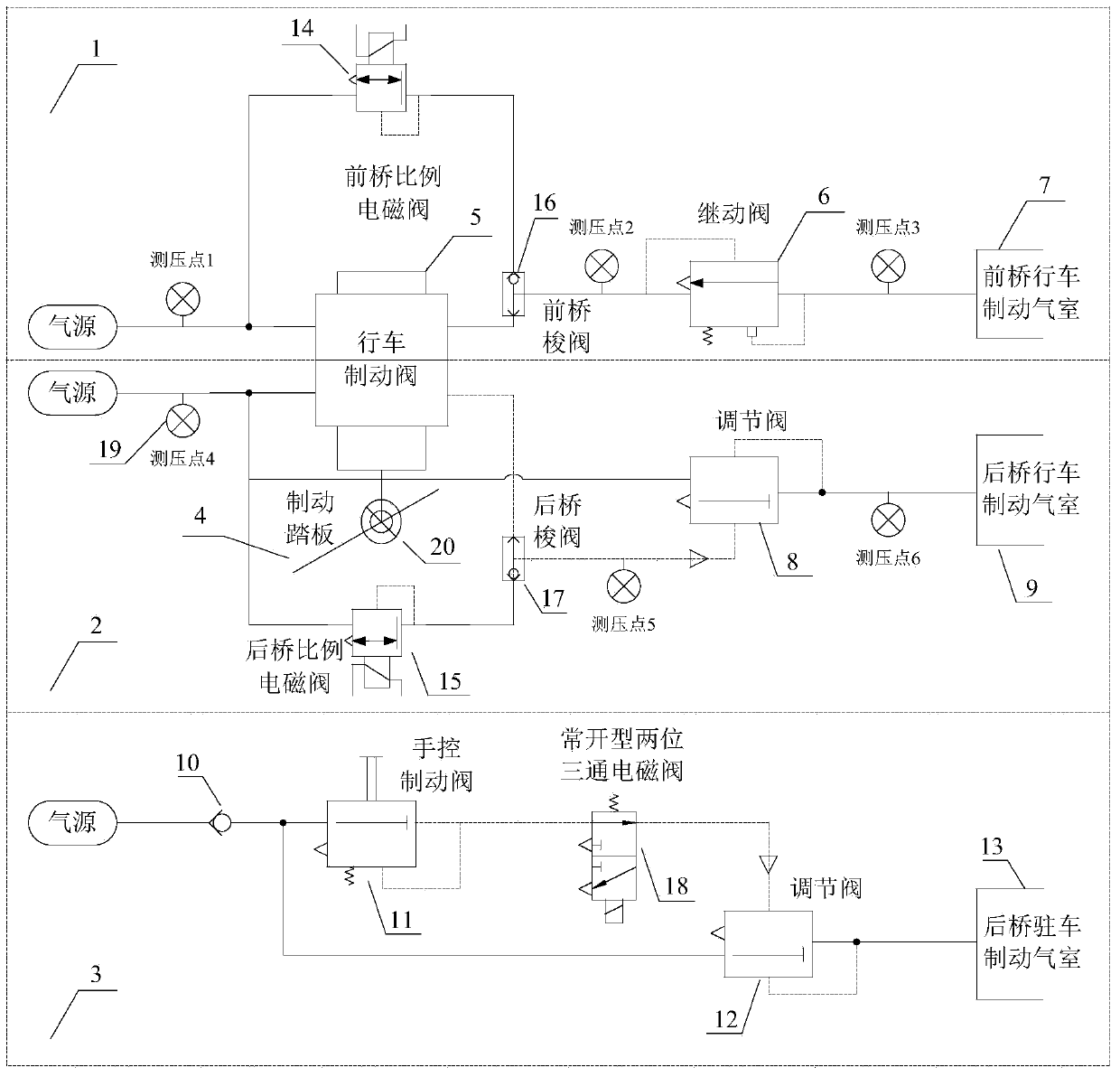
[0031]The original car air pressure brake system usually includes the front axle service brake system, the rear axle service brake system and the rear axle parking brake system; the front axle service brake system and the rear axle service brake system share the service brake valve; The front axle service brake system is mainly composed of the relay valve 6 and the front axle service brake chamber 7, the rear axle service brake system is mainly composed of the regulating valve 8 and the rear axle service brake chamber 9, the rear axle parking brake The braking system consists of a one-way valve 10, a manual brake valve 11, a regulating valve 12 and a rear axle parking brake air chamber 13. In the manual driving mode, the driver depresses the brake pedal 4, the service brake valve 5 is opened, and the service brake air chamber 7 of the front axle is in...


PUM


Abstract

The invention provides an electrically controlled pneumatic braking system of a vehicle. The system retains a manual braking function of a manual driving mode while achieving an electrically controlled braking function of an unmanned driving mode of the intelligent vehicle, the manual driving mode and the unmanned driving mode can be switched flexibly, and a remote control braking function is achieved on emergency circumstances. The system comprises a braking controller, a front axle proportional solenoid valve, a front axle shuttle valve, a rear axle proportional solenoid valve, a rear axle shuttle valve and a normally open type two-position three-way solenoid valve. The braking controller is used for receiving upper planning decision commands of the intelligent vehicle; when electrically controlled driving braking needs to be conducted, the braking controller controls the front axle proportional solenoid valve and the rear axle proportional solenoid valve to act, the air pressure output by the front axle shuttle valve is made to be the air pressure of an output port of the front axle proportional solenoid valve, and the air pressure output by the rear axle shuttle valve is made to be the air pressure of an output port of the rear axle proportional solenoid valve; when manual driving braking needs to be conducted, the braking controller enables the front axle proportional solenoid valve and the rear axle proportional solenoid valve to be powered off.

Description

technical field [0001] The invention belongs to the technical field of intelligent vehicles, and in particular relates to an electronically controlled pneumatic brake system for vehicles. Background technique [0002] With the development of the society and the progress of the economy, the number of cars in the world continues to increase, and the following problems, such as traffic safety, traffic congestion, energy shortage, and environmental pollution, have become common problems faced by all countries in the world. The traditional way to solve traffic problems is to build roads. However, the traffic system is a huge and complex system. It is difficult to solve the fundamental problem by improving the traffic capacity of the road network only from the perspective of expanding roads. In this context, the idea of ​​comprehensively considering the transportation infrastructure, transportation vehicles and traffic participants, and making full use of high-tech to solve traffi...

Claims


Application Information

Patent Timeline
IPC IPC(8): B60T13/68B60T13/74
Inventor 朱敏陈慧岩
Owner BEIJING INSTITUTE OF TECHNOLOGYGY
Why Eureka
Try Eureka