Lifting mechanism of schnabel car

A clamping car and clamping technology, which is applied in the direction of trucks, transport passenger cars, railway car body parts, etc., can solve the problems of not reducing the output pressure of the lifting cylinder, and the output pressure of the lifting cylinder is large, and achieve the effect of ensuring the smoothness of transportation.

Inactive Publication Date: 2014-12-10
YANSHAN UNIV
View PDF2 Cites 3 Cited by
  • Summary
  • Abstract
  • Description
  • Claims
  • Application Information

AI Technical Summary

Problems solved by technology

[0003] However, due to the high quality of the goods being transported and the specific structure of the lifting mechanism in the prior art, the output pressure of the lifting cylinder is always maintained at a large value during the lifting of the goods.
At present, there are existing materials, such as Chinese patent CN103101546A, which discloses that by adjusting the synchronization rate of the elongation of the lifting cylinder to improve the stress of the clamping vehicle during the lifting process of the cargo, but this patent does not reduce the output pressure of the lifting cylinder during the lifting process.

Method used


Image

  • Lifting mechanism of schnabel car
  • Lifting mechanism of schnabel car

Examples


Embodiment Construction

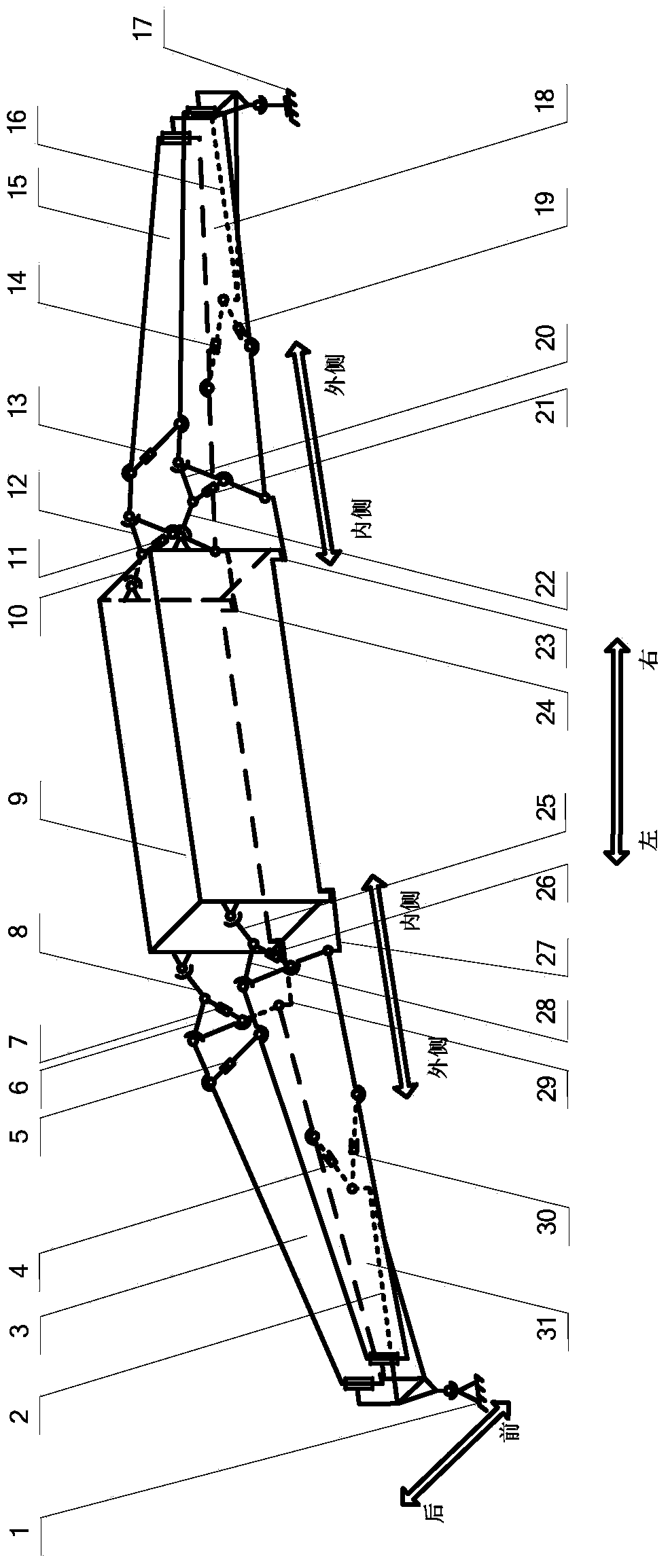
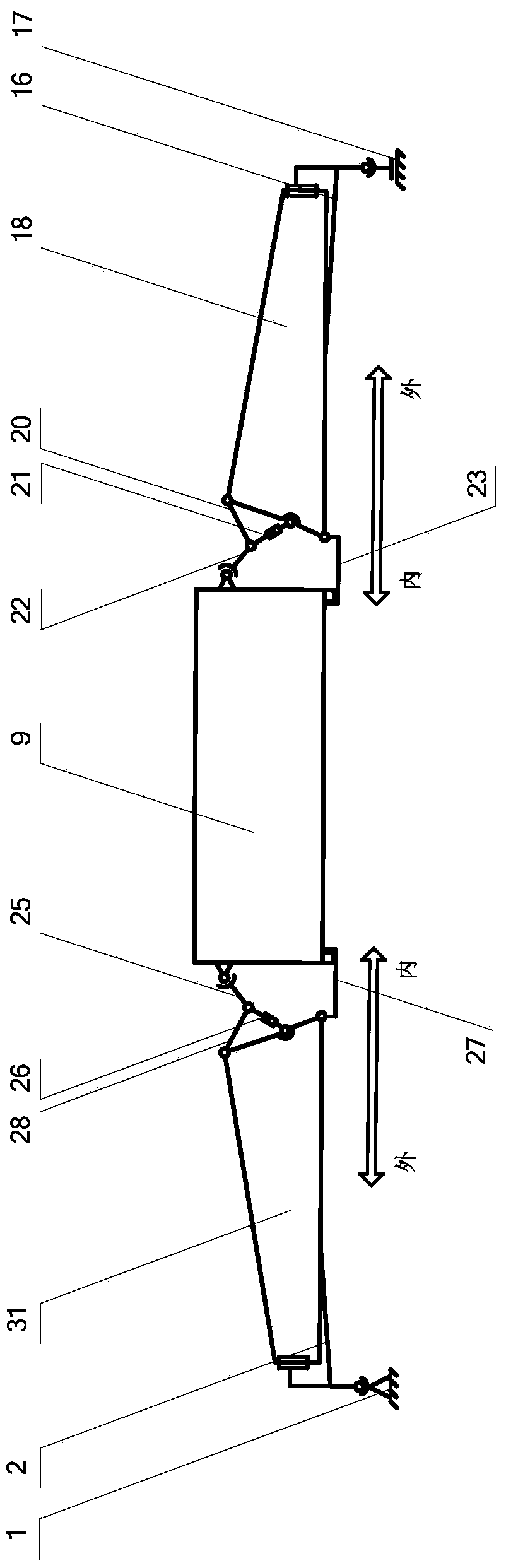
[0014] exist figure 1 and figure 2 In the schematic diagram of the lifting mechanism of the clamping vehicle shown in the schematic diagram, each half of the symmetrical two parts is called a half lifting mechanism of the clamping vehicle, and the inner sides of the two halves of the lifting mechanism of the clamping vehicle face each other; Fixed, that is, the center plate of each semi-clamping car is connected to the outer end of the above guide beam through a ball pair, and the outer end of the guide beam is hinged to the outer ends of the front and rear clamping beams above through two rotating pairs with vertical axes (visible from the front view) The jaw beam is the front jaw beam), the upper parts of the inner ends of the same and parallel front and rear jaw beams are respectively hinged with one end of the front and rear outer connecting rods through ball joints, and the other ends of the front and rear outer connecting rods are respectively rotated The pair is hinge...


PUM


Abstract

A lifting mechanism of a schnabel car is mainly characterized in that central disks of the outer ends of two half schnabel car lifting mechanisms are connected with the outer ends of guide beams through ball pairs, the outer end of each guide beam is hinged to the outer end of a front schnabel beam and the outer end of a rear schnabel beam, the upper portions of the inner ends of each front schnabel beam and the corresponding rear schnabel beam which are identical and connected in parallel are hinged to one end of a front outer connecting rod and one end of a rear outer connecting rod, the other end of the front outer connecting rod and the other end of the rear outer connecting rod are hinged to one end of a front inner connecting rod and one end of a rear inner connecting rod, the other end of the front inner connecting rod and the other end of the rear inner connecting rod are connected with the upper portions of goods, and a rotating pair of the front inner connecting rod, a rotating pair of the rear inner connecting rod, a rotating pair of the front outer connecting rod and a rotating pair of the rear outer connecting rod are respectively connected with a piston rod of a lifting oil cylinder, a cylinder body of each lifting oil cylinder is connected with the middle of the inner end of the corresponding schnabel beam, the lower portions of the inner ends of the two corresponding schnabel beams are hinged to one end of a front car lug and one end of a rear car lug, the other end of each front car lug and the other end of the corresponding rear car lug are connected with the lower ends of the goods, and a width regulating mechanism is installed between each front schnabel beam and the corresponding rear schnabel beam. According to the lifting mechanism of the schnabel car, small lifting force is exerted by the lifting oil cylinders so that the goods with the same weight can be lifted, and the lifting mechanism of the schnabel car has the advantage of saving labor.

Description

technical field [0001] The invention relates to a lifting mechanism of a railway transport tong car. Background technique [0002] With the rapid development of my country's national economy, petrochemical, electric power, aerospace, metallurgy and military equipment industries have also developed by leaps and bounds, and there are more and more large cargoes with heavy weight and complex shapes. higher requirements. These large goods are collectively referred to as long goods in railway transportation, and there are three main types of trucks for transporting these long goods, namely large concave bottom cars, clamp cars and drop hole cars, among which clamp cars are the current railway special freight market. One of the main models, it plays a huge role in the transportation of large-scale cargo. It has more functions and has a hydraulic lifting device to make the shipment of cargo more flexible. It is suitable for cargo with self-supporting capacity of different widths, s...

Claims


Application Information

Patent Timeline
Patent Type & Authority Applications(China)
IPC IPC(8): B61D3/00B61D45/00
Inventor 赵延治王向南白学刚束龙任玉波
Owner YANSHAN UNIV
Why Eureka
Try Eureka