Multi-wheel lift drive system

A lifting drive, multi-wheel train technology, applied in the direction of transmission, transmission parts, belts/chains/gears, etc., can solve the problem of unable to guarantee the synchronous lifting of the tank, save labor costs, reduce accumulated errors, guarantee The effect of production efficiency

Active Publication Date: 2017-02-15
北京科创环能装备技术有限公司
View PDF7 Cites 0 Cited by
  • Summary
  • Abstract
  • Description
  • Claims
  • Application Information

AI Technical Summary

Problems solved by technology

[0007] The purpose of the present invention is to provide a multi-wheel lifting drive system to overcome the technical problem that the existing drive equipment cannot guarantee the synchronous lifting of the tank due to the cumulative error of the chain

Method used


Image

  • Multi-wheel lift drive system
  • Multi-wheel lift drive system
  • Multi-wheel lift drive system

Examples


Embodiment Construction

[0025] The specific embodiments of the present invention will be described in detail below in conjunction with the drawings.

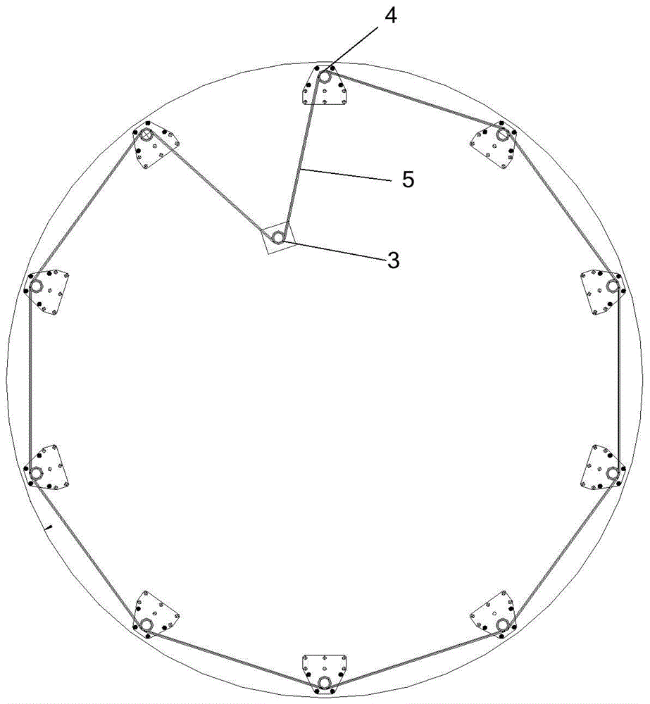
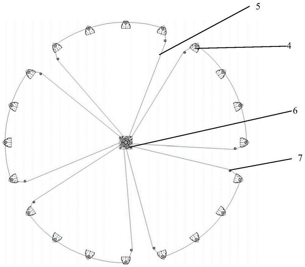
[0026] Such as image 3 with Figure 4 As shown, this embodiment provides a multi-wheel train lifting drive system, including a drive device 6 and a plurality of sprockets 10; the drive device 6 includes a reducer 3 and a gear transmission mechanism; the reducer 3 passes through the gears The transmission mechanism drives the plurality of sprockets 10; the lifting mechanism adopts the elevator 4 to lift the assembly board. The reducer 3 is generally set at the middle position of the assembled tank; each sprocket 10 is correspondingly connected with one or more elevators 4 through a chain 5. In the invention, a gear transmission mechanism is matched with a sprocket, and a lifting mechanism is driven by a single chain, so that during the assembly process of the assembly board around the biogas tank body, the same layer assembly board is lifted to the set he...


PUM


Abstract

The invention relates to the field of manufacture of methane tanks, in particular to a multiple-gear-train lifting driving system which comprises a speed reducer, a gear transmission mechanism and a plurality of chain wheels. The speed reducer drives the plurality of chain wheels through the gear transmission mechanism, and each of the chain wheels is connected with one or more lifting mechanisms through a chain correspondingly. According to the multiple-gear-train lifting driving system, the gear transmission mechanism drives a plurality of chains to drive the lifting mechanisms, the plurality of chains are utilized, lengths of the chains are shortened, accumulation errors of the chains are greatly reduced, the errors are controlled within a permissible range, synchronous lifting of assembly plates around large and middle methane tanks is ensured, labor cost is reduced, and production efficiency is ensured.

Description

Technical field [0001] The invention relates to the field of biogas tank manufacturing, in particular to a multi-wheel train lifting drive system. Background technique [0002] As a new form of biogas tank body, biogas assembly tanks are increasingly used in the biogas industry. Such as figure 1 As shown, during the installation process of the assembled tank, the entire circle of assembled panels 2 on the same layer on the assembled tank body 1 needs to be lifted up to the same specified height along the elevator, and then the next layer of assembled panels 2 is installed on the elevator. Then it is lifted by the elevator, so that the assembly board 2 is installed layer by layer, and the cycle is repeated until the installation is completed. This installation method requires special auxiliary drive equipment to synchronize the lifting of the assembled board. [0003] Such as figure 2 As shown, the existing driving equipment mainly includes a reducer 3 and a sprocket (not shown i...

Claims


Application Information

Patent Timeline
Patent Type & Authority Patents(China)
IPC IPC(8): F16H7/06F16H7/08F16H57/028B66D1/20
CPCB66D1/20F16H7/06F16H7/08F16H37/027
Inventor 符立伟时军梁艳辉
Owner 北京科创环能装备技术有限公司
Why Eureka
Try Eureka