
Conveying device for substrates of touch screens

A technology for conveying devices and screen substrates, applied in the field of machinery, can solve problems such as scratches, abrasions, stains and powder layers on the substrates, touch marks on the surface of the substrates, and easy to produce surfaces, etc., to achieve protection Good effect, good guiding effect, high cleanliness effect

Active Publication Date: 2014-12-10
河源力友通讯科技有限公司
View PDF6 Cites 4 Cited by
  • Summary
  • Abstract
  • Description
  • Claims
  • Application Information

AI Technical Summary

Problems solved by technology

[0004] Although the loading and unloading device disclosed in this patent can realize cyclic loading and unloading, and has high processing efficiency, it has the following disadvantages: 1. Tiled placement is easy to produce surface dust; 2. Tiled placement leads to limitations in transportation methods 3. The substrate is transported through the conveyor belt, and the substrate will be in contact with the conveyor belt, so it is difficult to avoid scratches, abrasions, stains and powder layers on the substrate. Defects, therefore, it is necessary to design a conveying device for touch screen substrates

Method used


Image

  • Conveying device for substrates of touch screens
  • Conveying device for substrates of touch screens
  • Conveying device for substrates of touch screens

Examples


Embodiment 1

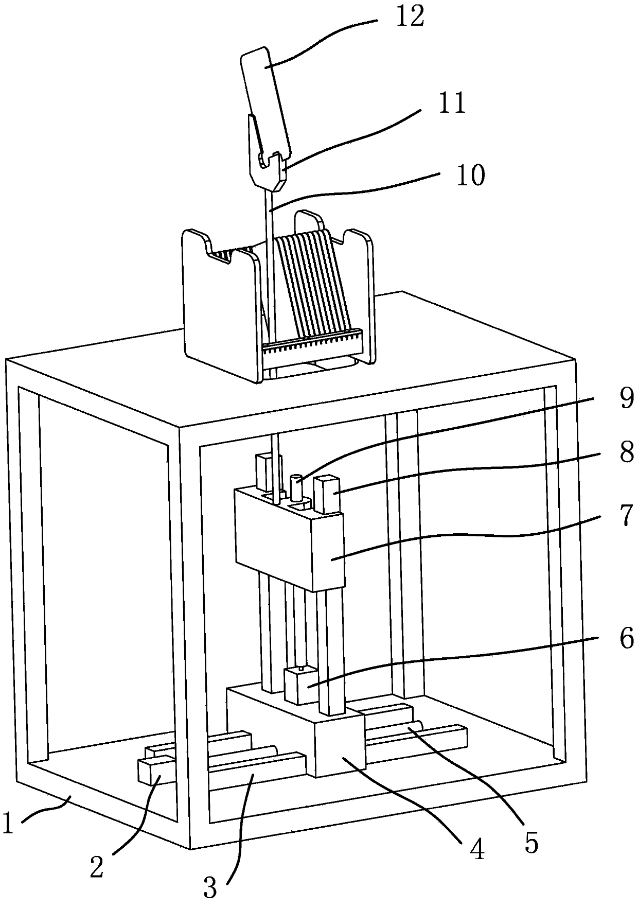
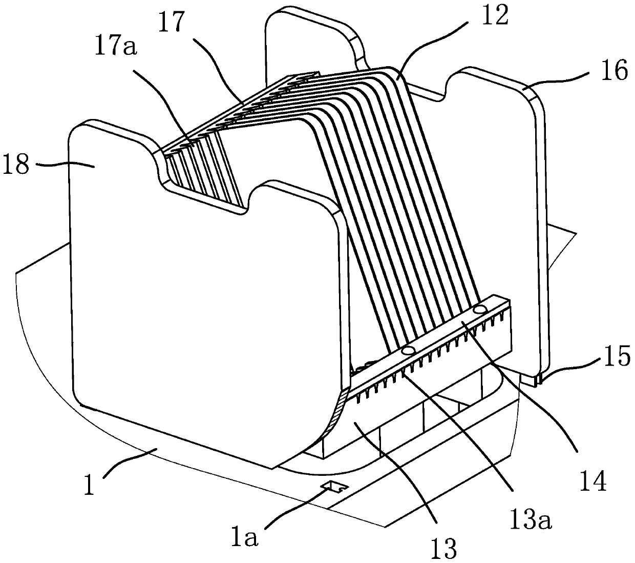
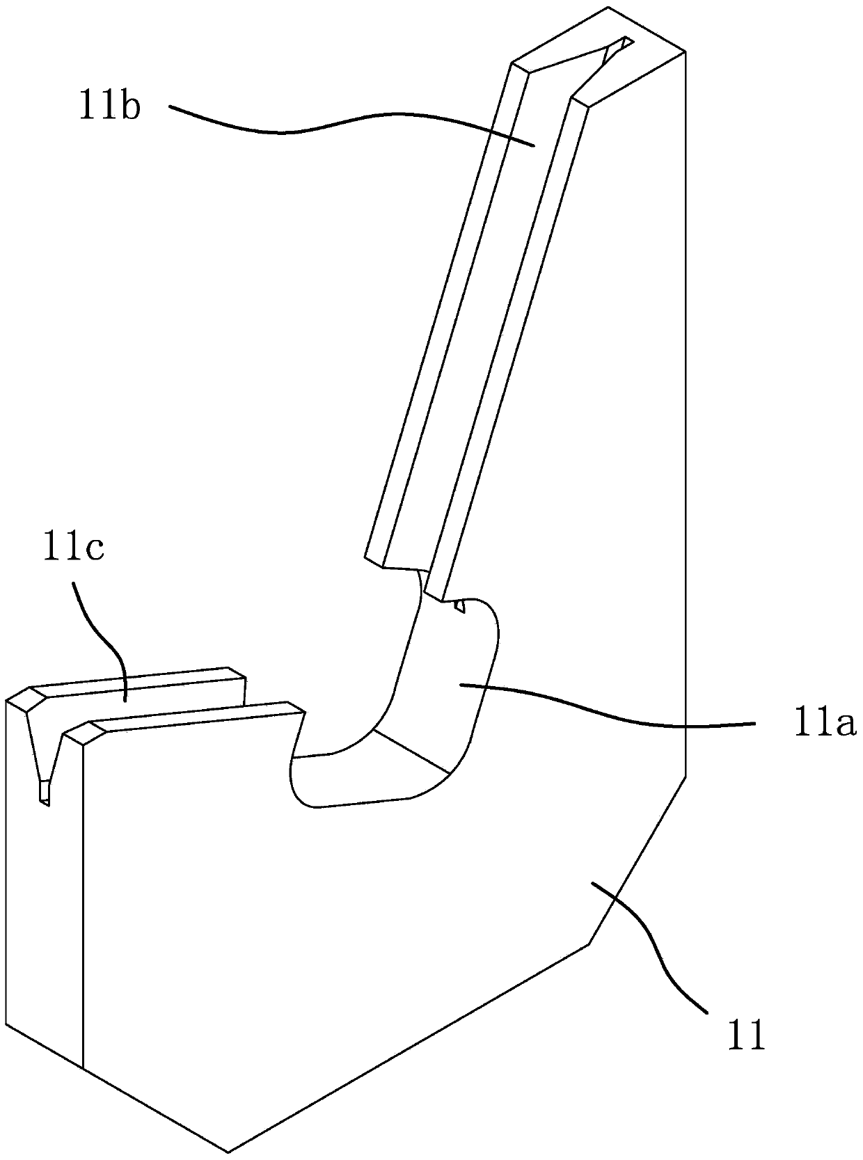
[0044] like figure 1 , figure 2Shown, the delivery device of this touch screen substrate comprises a frame 1, and this device comprises the storage box that is box-shaped and is connected on the frame 1 and the bracket 11 that is positioned at the bottom of the storage box, and the bottom of the storage box has Positioning block 15, a positioning hole 1a is provided on the frame 1, and the positioning block 15 at the bottom of the storage box is fixed in the positioning hole 1a on the frame 1, so that the storage box is connected on the frame 1; the storage box One side of the storage box has a plurality of positioning grooves 17a recessed in a strip shape, and the other side of the storage box has several positioning grooves 13a with the same number as the positioning grooves 17a and one-to-one corresponding positions. Positioning parts for positioning the adjacent two edges of the touch screen substrate 12 are formed between the positioning groove one 17a and the positioni...

Embodiment 2

[0056] The content in the second embodiment is roughly the same as that in the first embodiment, except that the driver one in the first embodiment is above the second driver; and in the second embodiment, as Figure 4 As shown, the first driving member in the second embodiment is below the second driving member.


PUM


Abstract

The invention provides a conveying device for substrates of touch screens, and belongs to the technical field of machines. The conveying device for the substrates of the touch screens solves the technical problems that because substrates are placed flat in an existing feeding and discharging device, dust can easily accumulate on the surfaces of the substrates, and touch marks can be easily left on the surfaces of the substrates. The conveying device for the substrates of the touch screens comprises a rack. The conveying device comprises a box-shaped storage box connected to the rack and a supporting frame located below the storage box, wherein a plurality of strip-shaped concave first positioning grooves are formed in one side in the storage box, a plurality of second positioning grooves are formed in the other side in the storage box, and the first positioning grooves and the second positioning grooves are the same in number and corresponding in position one to one. The conveying device for the substrates of the touch screens further comprises a first driving part, wherein both the first driving part and the supporting frame are located below the storage box, and the first driving part can drive the supporting frame to penetrate through a positioning portion to move vertically. The conveying device for the substrates of the touch screens has the advantages of being wide in application range and capable of achieving the advantages that no dust accumulates on the surfaces of the substrates and the surfaces of the substrates are not touched during transportation.

Description

technical field [0001] The invention belongs to the technical field of machinery, and relates to a conveying device, in particular to a conveying device for a touch screen substrate. Background technique [0002] At present, in the touch screen production process, the storage and transportation medium of the touch screen substrate is still to use the plastic frame to lay the substrate, the foam box to place the substrate vertically, or the V-shaped groove ladder frame to stack the substrate horizontally, and the transportation method between processes is also inevitable. It is necessary to touch the surface of the touch screen substrate with hands or parts, and the overall transport box transmission mechanism cannot reach the 100% non-touch state. [0003] After searching, for example, Chinese patent literature discloses an automatic loading and unloading device for printing window glass protective screens [Patent No.: ZL 201320644202.0; Authorized Notice No.: CN 203529435U]...

Claims


Application Information

Patent Timeline
IPC IPC(8): B65G47/74B65G47/82
CPCB65G49/061
Inventor 徐景丽
Owner 河源力友通讯科技有限公司
Learn More